
The ultimate LiFePO4 battery? Epoch’s 460ah powerhouse
My wife Laura reads most of my entries. She often tells me that I write about lithium batteries too much. Well, sorry but what follows will be another article about another lithium battery. If it helps, this is one hell of a battery and I think everyone considering new deep-cycle batteries for their boat should know about it and consider it. That’s doubly true in light of the significant step forward in battery safety I found when I opened the lid of my evaluation unit.
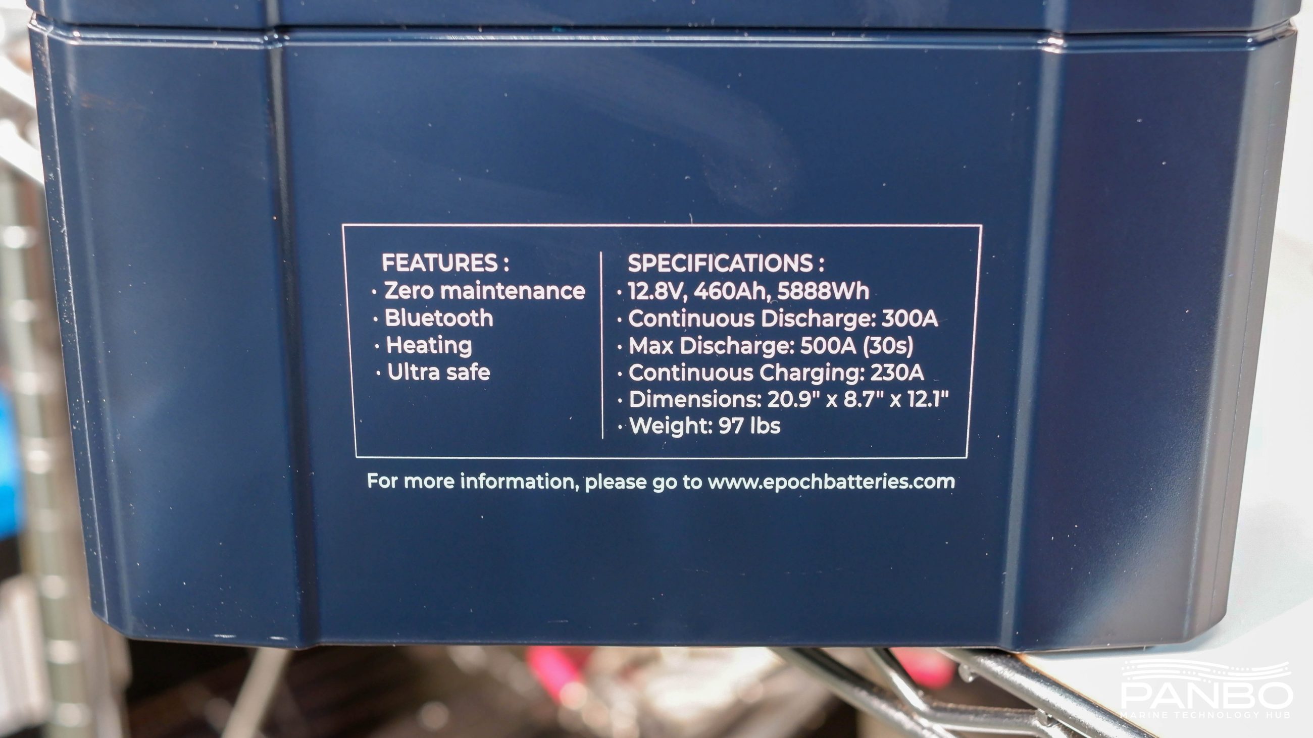
For the last several weeks I’ve been testing Epoch’s powerhouse 12-volt, 460-amp-hour, 8D sized, IP67, heated, Bluetooth, and Victron communicating battery. That’s a lot of features lined up in the name of the battery, but each of them is worth highlighting. This battery checks the box for nearly every feature I could think of wanting and adds several features I wasn’t even aware I wanted.
The battery
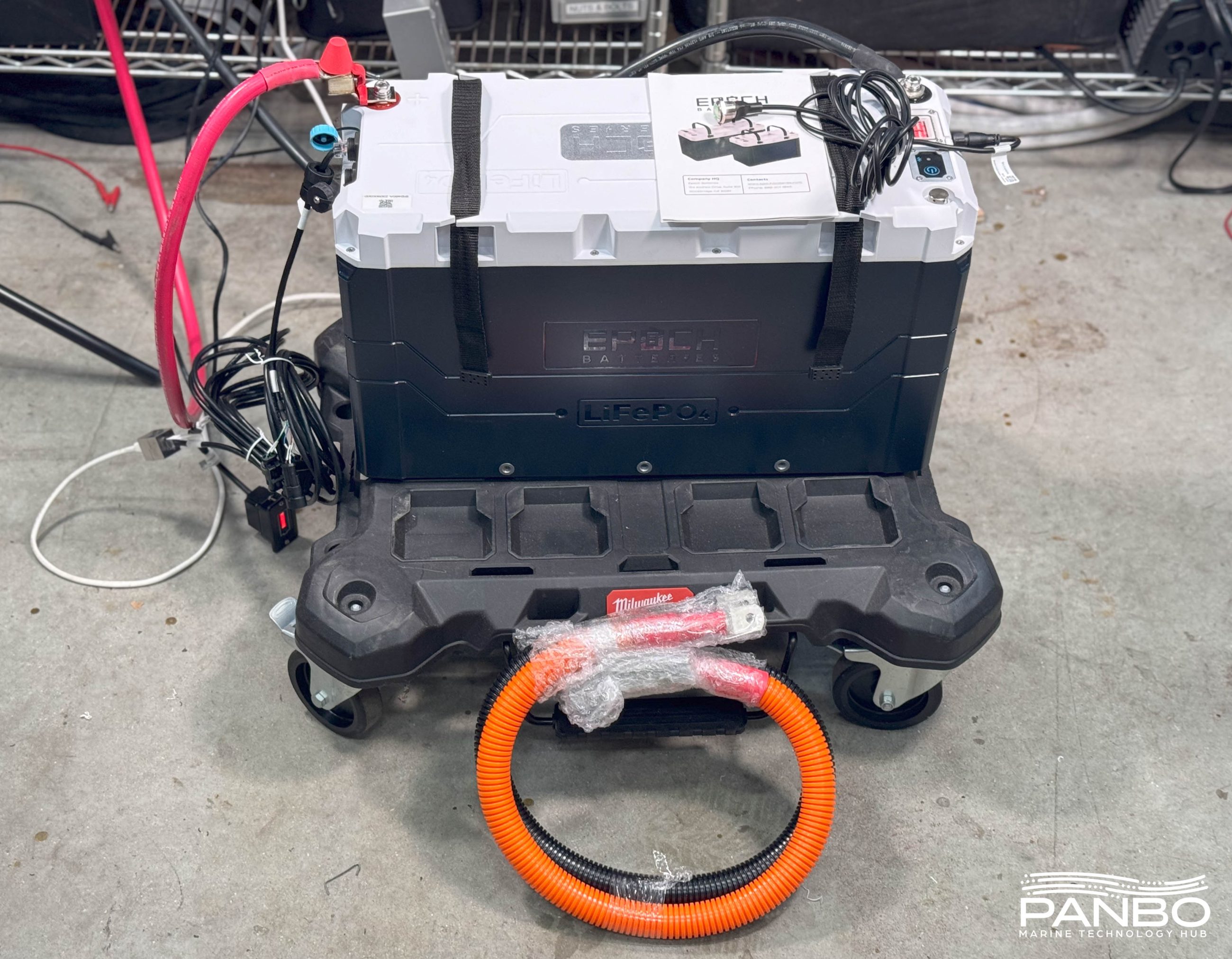
Each 12-volt, 460-amp-hour battery costs $1,999. The battery ships with a 10-segment LED display, remote-power switch, Victron communications cable, and mounting brackets. Although my early unit didn’t include it, I’m told that Epoch will include the custom cable required for daisy-chaining batteries to Victron systems. Lastly, my early unit did include an Anderson Power Pole to 4 AWG cable but I’m told that probably won’t be the case in the future.
If, after reading this lengthy review of the battery, you decide you would like to purchase one or more, I encourage you to use this link: https://www.epochbatteries.com/?rfsn=7030270.54d2cb and the coupon code MARINEHOWTO. The link and coupon code will earn you 10 percent off your order as well as help Rodd Collins of MarineHowTo.com. Rodd suffered a stroke and has had to shut down his marine electrical business. For those who haven’t come across his site, it is a wealth of information and Rodd is a frequent source of expertise and analysis for me.
Costs compared
| Battery | Voltage | Chemistry | Amp hours @ 20hr rate | Recommended DoD | Useable Amp hours | Useable watt hours | Cost | $/useable watt hour |
| Duracell GC2 | 6 | FLA | 215 | 50% | 107.5 | 645 | $119.88 | $0.19 |
| Kilovault HLX+ 3600 | 12 | LiFePO4 | 300 | 80% | 240 | 2880 | $1,125.00 | $0.39 |
| Epoch 460ah12v | 12 | LiFePO4 | 460 | 80% | 368 | 4416 | $1,999.00 | $0.45 |
| West Marine 8D AGM Dual Purpose | 12 | AGM | 245 | 50% | 122.5 | 1470 | $1,064.99 | $0.72 |
| Lifeline 8D deep cycle | 12 | AGM | 255 | 50% | 127.5 | 1530 | $1,164.99 | $0.76 |
| Battleborn 8D | 12 | LiFePO4 | 270 | 80% | 216 | 2592 | $2,399.00 | $0.93 |
The table above gives an overview of the cost of the Epoch 460 compared to several other options. A couple of years ago I did a writeup on the vagueries of comparing the cost of LiFePO4 batteries to other chemistries. In addition to the considerations I raised, several commenters had good points about the other factors. To keep the discussion short here, I’ll just point out I’m not comparing battery longevity (an area in which LiFePO4 has a significant advantage over any lead-based chemistry), resting voltage differences, charge acceptance rates, or charge efficiency here. The only thing I’m looking at here is a rough comparison of the cost per usable watt hour.
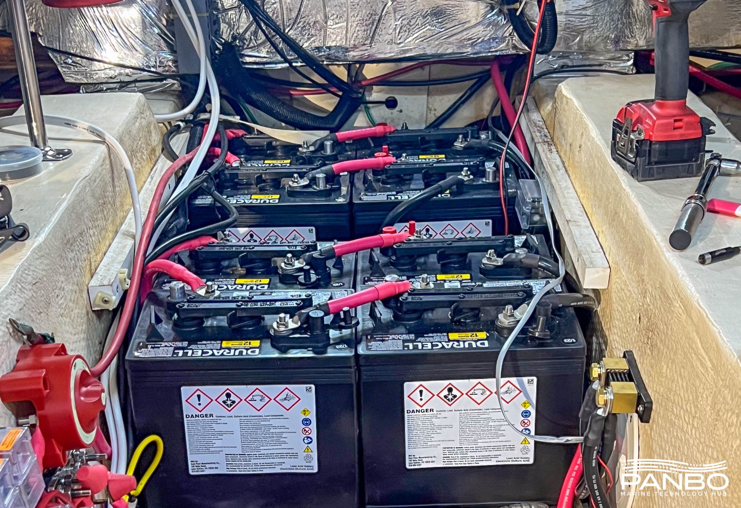
Anyone purchasing 460 amp-hour batteries is likely looking to construct a large house bank. I believe BMS-managed batteries are best deployed in, at least, pairs to ensure resiliency in the event of a BMS failure. So, if that practice is followed, the smallest battery bank possible would be a 960 total amp-hour bank with 768 amp-hours useable assuming an 80-percent depth of discharge. Let’s just compare that for a minute to a bank constructed of GC2 or 8D AGM batteries.
A pair of Epoch 460s would produce 8,832 useable watt-hours. To get the same useable watt hours from GC2 batteries we would need 13.7 GC2s. Let’s call that 14 batteries. If instead, we construct the bank from Lifeline 8D batteries, we would need 5.77 batteries. Again, we can round up to 6 batteries. As we compare costs we should also factor in the labor of installing batteries, the cost of battery cable, battery terminals, heat-shrink, and other miscellaneous supplies. For Epoch 460s, we would need a total of four cables, two positive and two negative. The GC2s would require 28 cables and the Lifeline 8D would require 12.
| Battery | Size | Cubic inches | Weight (lbs) | Useabele wh | wh / cubic inch | wh / pound |
| Duracell GC2 | 10.25×7.125×10.875″ | 794.21 | 60.5 | 645 | 0.81 | 10.66 |
| Kilovault HLX+ 3600 | 20.5x11x9.25″ | 2085.88 | 88.2 | 2880 | 1.38 | 32.65 |
| Epoch 460ah12v | 20.8×12.1×8.7″ | 2189.62 | 97 | 4416 | 2.02 | 45.53 |
| West Marine 8D AGM Dual Purpose | 20.75x11x10″ | 2282.50 | 161 | 1470 | 0.64 | 9.13 |
| Lifeline 8D deep cycle | 20.75×10.89×8.6″ | 1943.32 | 156 | 1530 | 0.79 | 9.81 |
| Battleborn 8D | 21.29×11.59×10″ | 2467.51 | 81 | 2592 | 1.05 | 32.00 |
Another frequent means of comparing LiFePO4 batteries to other chemistries is by weight and size. The table above shows the lithium chemistries all enjoy a significant advantage in watt hours per pound. The Epoch is the leader at over 45-watt hours per pound. But even the lowest density LiFePO4 battery, the battleborn at 32 wh/lb is more than three times as dense as the densest lead-acid battery. The energy density by volume isn’t quite as stark, but the Epcoh 460 is more than twice as dense as the lead acid batteries.
There’s a fuse, in the battery!
Let’s get one exciting thing out early. These batteries contain a 500 amp fuse under the cover of the battery, just before the positive post of the battery. The fuse Epoch uses is from the EV market and carries an amp interrupt capability (AIC) of 50,000 amps. That rating means that with up to 50,000 amps flowing through the fuse, it will still successfully trip to an open and safe condition.
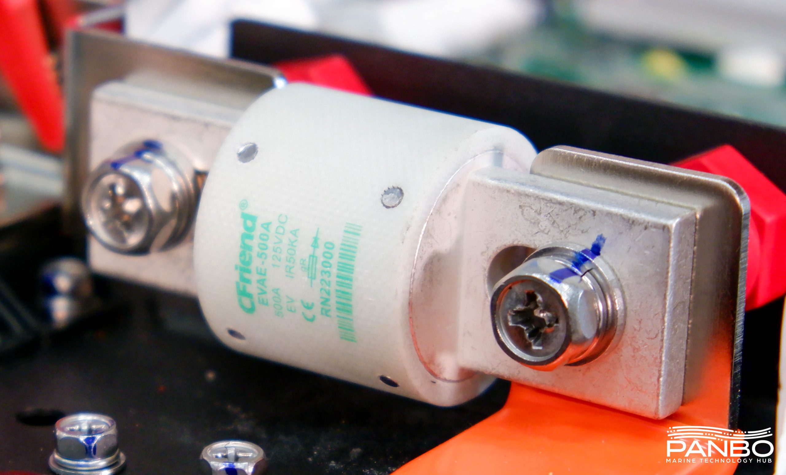
ABYC’s electrical safety standards require a fuse with a 20,000 amp AIC. Before disassembling this battery, I’d never seen a class T rated above 20ka AIC. Thus far the only gripes I have about the fuse are that it appears difficult to source a replacement — which I’m hoping Epoch can help with by selling replacements — and I think Epoch should label the outside of the battery to warn there’s a fuse inside. That way, a boat owner won’t find themselves stumped if they accidentally trip the fuse.
But, make no mistake this fuse is a really big deal and a really good thing. By placing a high AIC fuse inside the battery, installers are now relieved of the obligation to place a physically large class T fuse as close to the batteries as possible. The combination of fuse holder size and thick cables can make this a challenge. Knowing the fuse is inside the battery, an MRBF post-top fuse holder can now be safely used. Thus, the entire system is protected via the internal fuse, and the wire off the battery is protected by an appropriately sized MRBF on the positive terminal.


One bit of bad news is that while the fuse in the battery is great, it is a different form factor than the Class T fuses we all source from Bluesea and others. The fuse in the battery has slotted holes at a wider pitch than a typical class C. I’ve been calling the fuse in the battery a class T and did in my video above, but now I think that might not be right.
Performance
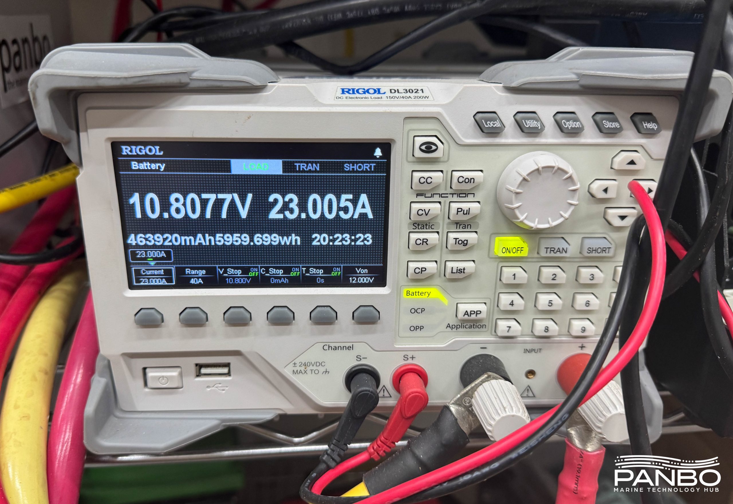
The basic performance of the 460 is pretty boring, and that’s a good thing. The battery is rated for 460 amp hours of capacity discharged over 20 hours. That means that if the battery is discharged at a fixed current (23 amps) it will deliver that over 20 hours. I’ve run at least a half-dozen such tests and it’s come out over spec each time. Voltage has been rock-solid and shows no issues whatsoever.
Perhaps the more interesting performance tests come from high discharge rates and how the battery performs. Keep in mind, this battery is rated for 300 amps of continuous discharge and 500 amps of discharge for up to 30 seconds. That’s a lot of power! At 25 C (or about 77 Fahrenheit) a Victron Multiplus II 3000 can output 2,400 watts at 93 percent efficiency. So, it shouldn’t consume more than 2,600 watts on a sustained basis. That means it will consume less than 215 amps at maximum capacity. Earlier, I mentioned I think LiFePO4 batteries should be deployed in a minimum of two batteries in parallel. Given the output ratings of these batteries, that means that even in the event of a failure of a battery, the surviving one could power all the boat’s needs.
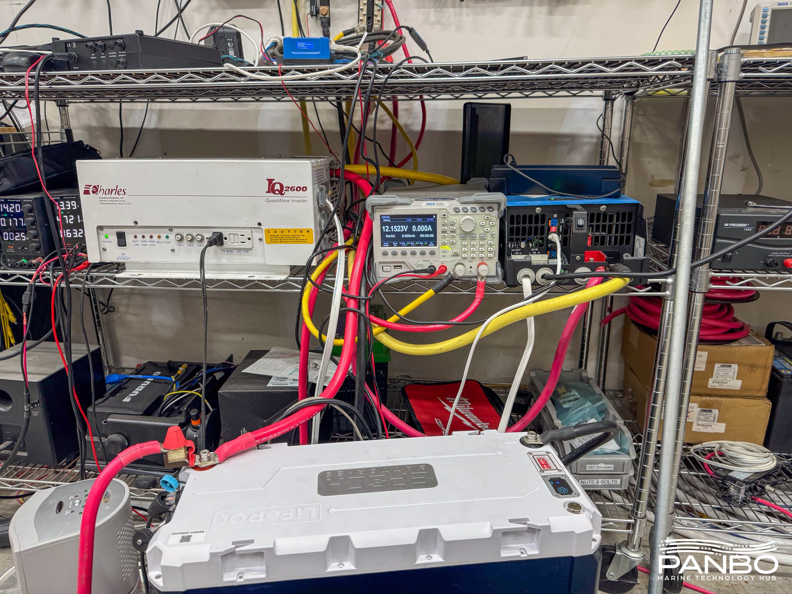
This battery has both the highest capacity and highest discharge and charge ratings of any I’ve tested. As a result, I had to beef up my load-generating abilities. I’ve typically used the MultiPlus II 2000 on the right side of the picture above. But, the 460 just shrugged at the less than 150 or so amps of load that a single inverter could generate. So, I went digging through my shelves of old gear and pulled out the behemoth Charles / Vanner IQ2600 that I pulled off Have Another Day. The two inverters were able to generate enough load to at least make the battery notice.
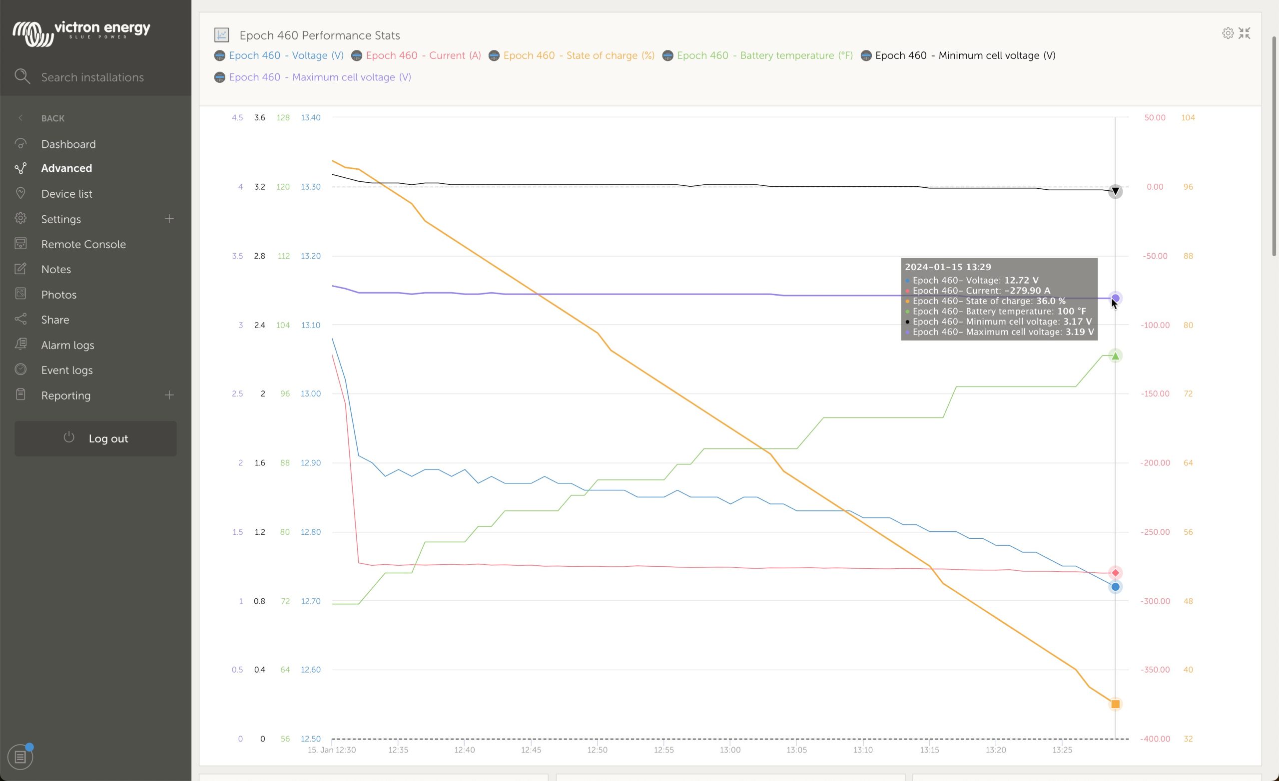
There’s a lot of data on the chart above, but shows how the battery stands up to a load. In this case, that load is about 3,500 watts of heaters. That 3,500 watts equates to around 280 amps of current at 12.7 or so volts. In the chart above, voltage is the blue line and it’s holding up nicely. When the load first hit, voltage dipped to about 12.9 volts. After 50 minutes of the load, and a drop of about 70 percent SOC, voltage is still holding over 12.7. In another good sign, the battery’s reported temperature has risen from 72 to 100 degrees during this sustained load.
I took the thermal image above after discharging the battery at just over 300 amps for about an hour and 15 minutes. As you can see, the heat sink on the top of the battery got quite warm. Interestingly, you can also see a hot spot where the fuse resides on the left side of the battery. Lastly, all the connections are pretty warm, not shocking in light of how much current they’re passing. Bear in mind that I’m pulling far more current from this single battery than is likely in most scenarios. Deployed in even a 2P configuration, it’s doubtful the battery would ever see these types of load. My testing represents worst-case scenario loads and the battery has stood up to those loads admirably.
Minimum current sensitivity
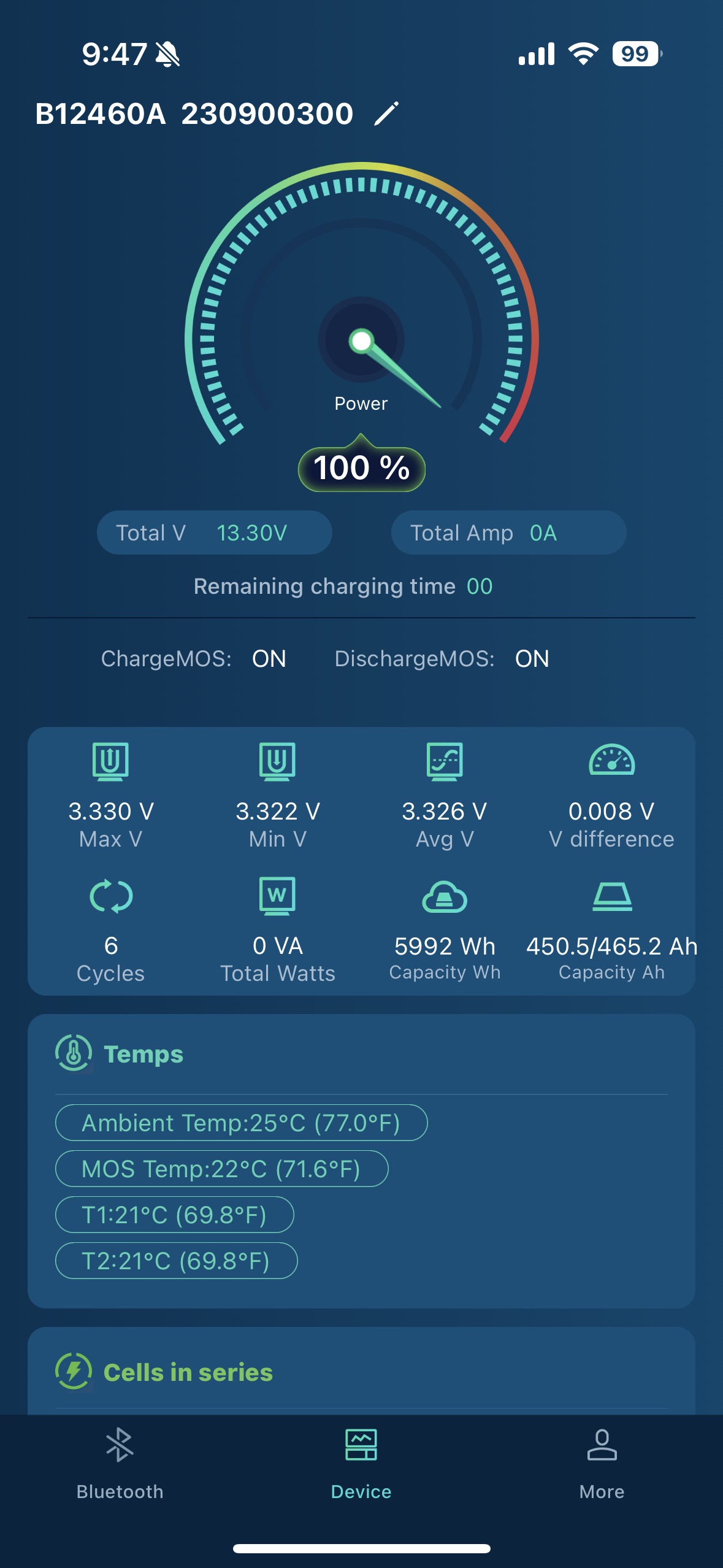
Towards the end of testing, I came across a limitation of the 460 amp-hour battery’s BMS’ measurement capabilities. It boils down to this: the battery can’t measure current draws below 1.4 amps. As a result, small current consumption simply isn’t measured by the battery. The screenshot above shows the result of not measuring a small, continuous load. In this case, it’s a 1.2 to 1.3 amp load from my two test inverters idling. I left the battery that way overnight and here’s where I ended up. The SmartShunt on my test bench correctly sees the battery at about 93 percent state of charge. But, because the battery’s BMS didn’t measure the low current draw, it still thinks the battery is at 100%.
Current flow through the battery is measured using current sensing resistors (CSR). Due to the high current handling of the battery, Epoch has to use a CSR that is capable of detecting large current. Unfortunately, especially in PCB mounted CSRs, those that have high current handling capabilities also have relatively high sensitivity floors.
I think this is a real limitation and one for any user of these batteries to understand. The battery won’t register any current below 1.4 amps. That showed up in my testing with one battery. But, imagine you’ve built a house bank of four of these batteries. Now, your loads are divided across all four batteries meaning you will need 5.6 amps to hit the sense floor of each of the four batteries. I think that’s a real enough issue to demand a Coloumb counting shunt in the mix like a Victron SmartShunt or BMV.
Connectivity

One of the major headline features of this new battery is built-in Victron communications. The 100 amp-hour batteries I tested previously have communications ports described as CANBus, but we never saw external integration with them. In fairness, I don’t believe Epoch ever promised communications with those batteries, though I thought it would come. Unlike the 100 ah batteries, this series launched with external communications working. As soon as I plugged the RJ-45 plug into the BMS.CAN port on my test Cerbo, information began flowing.
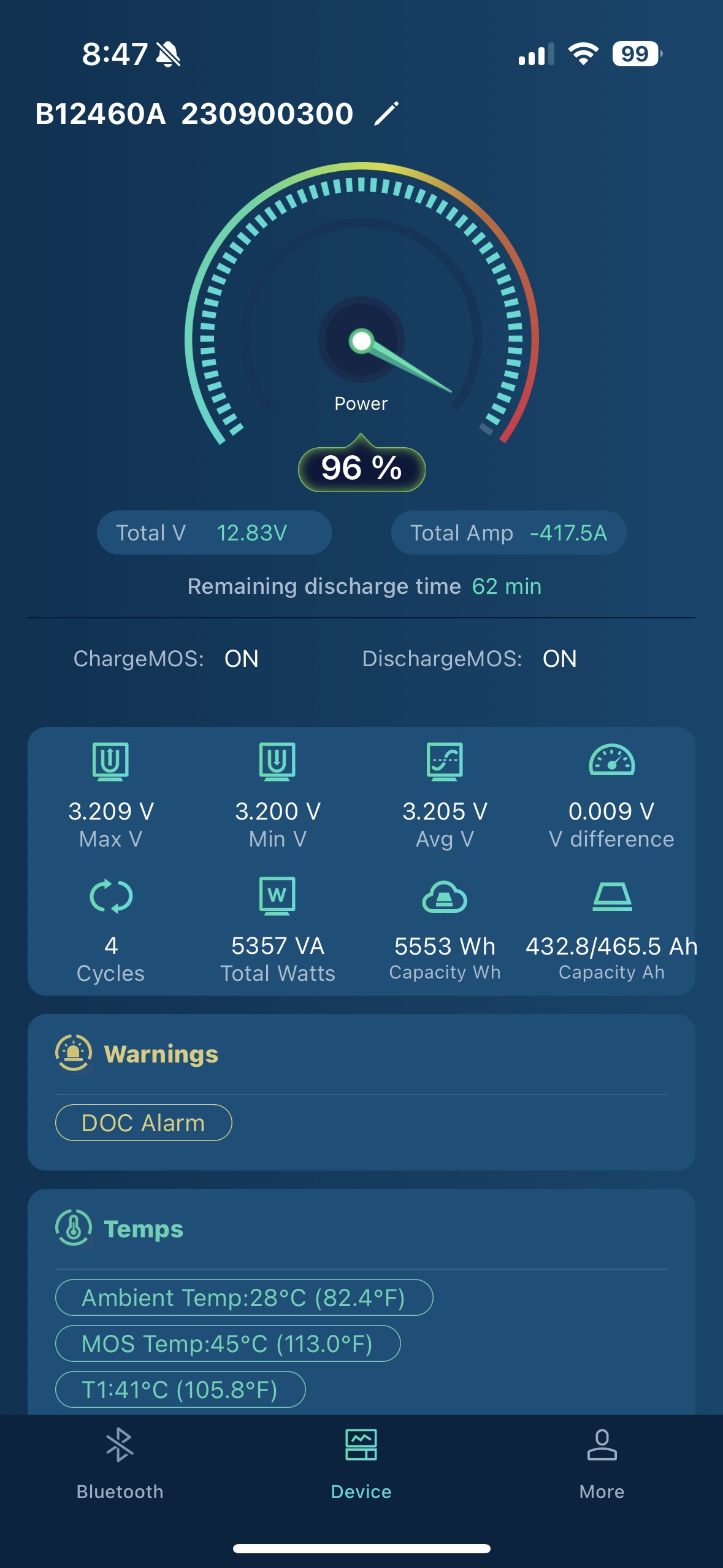
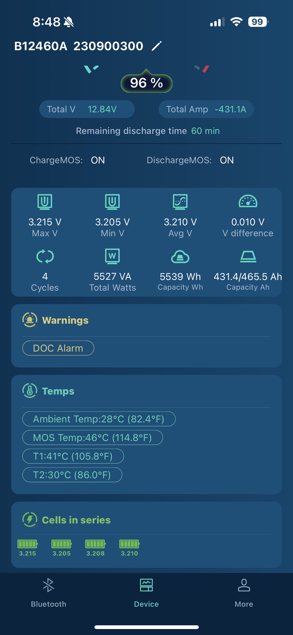
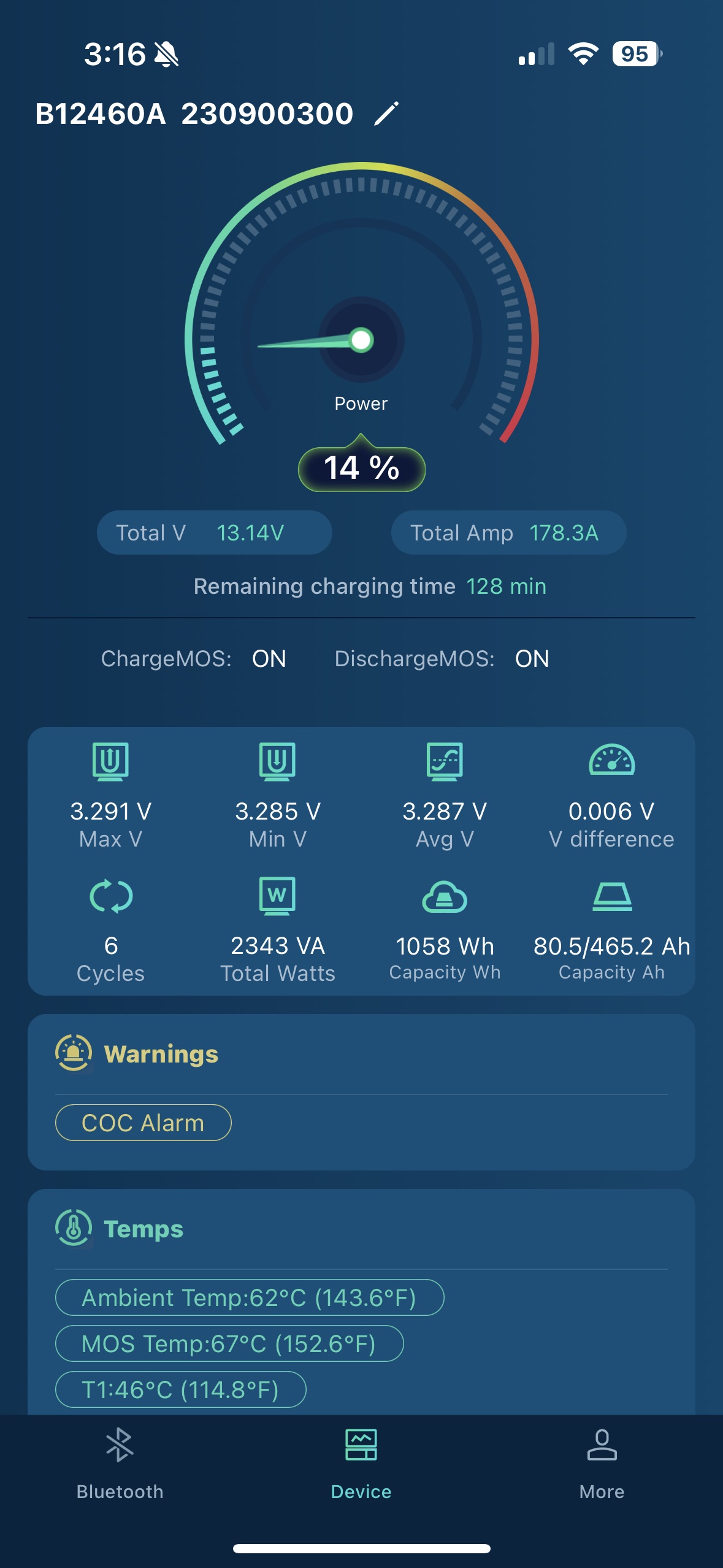
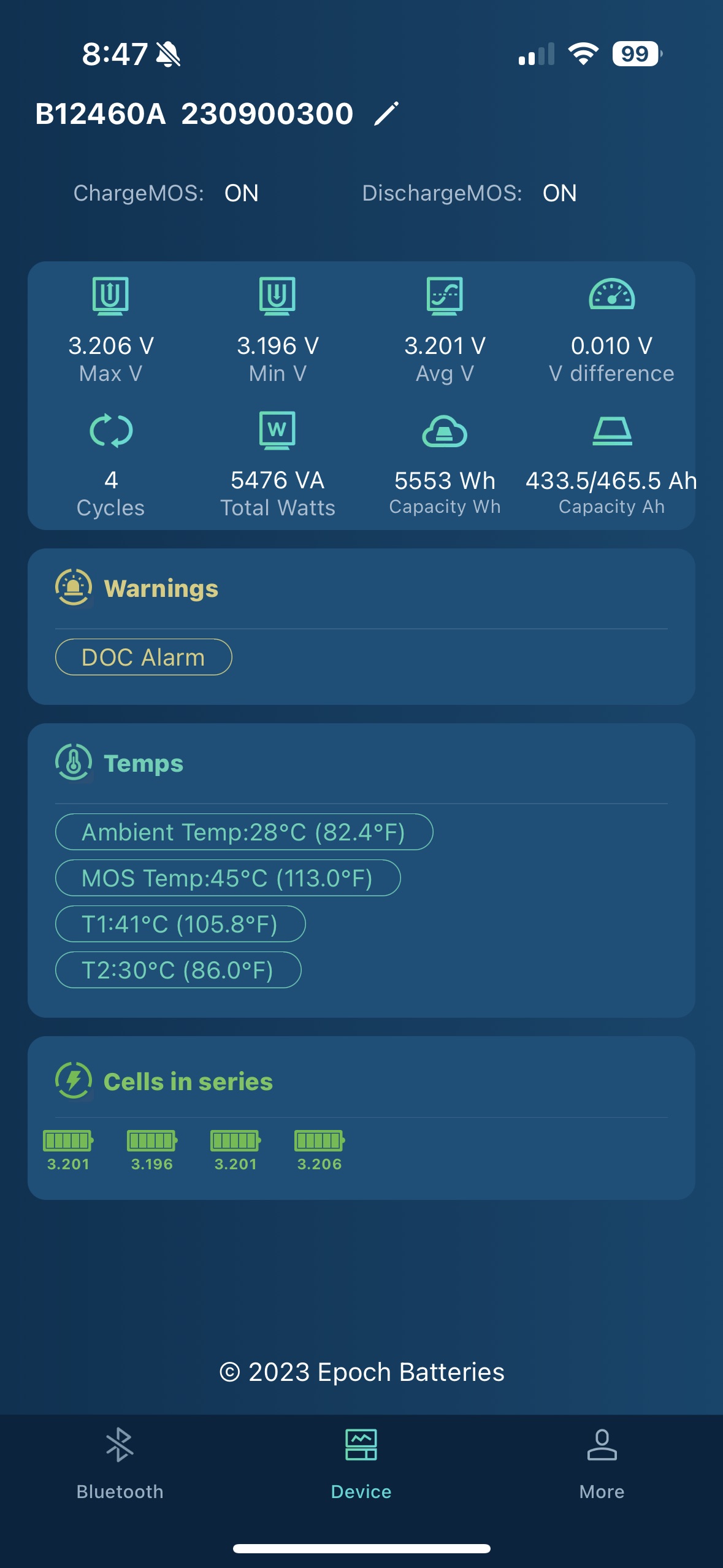
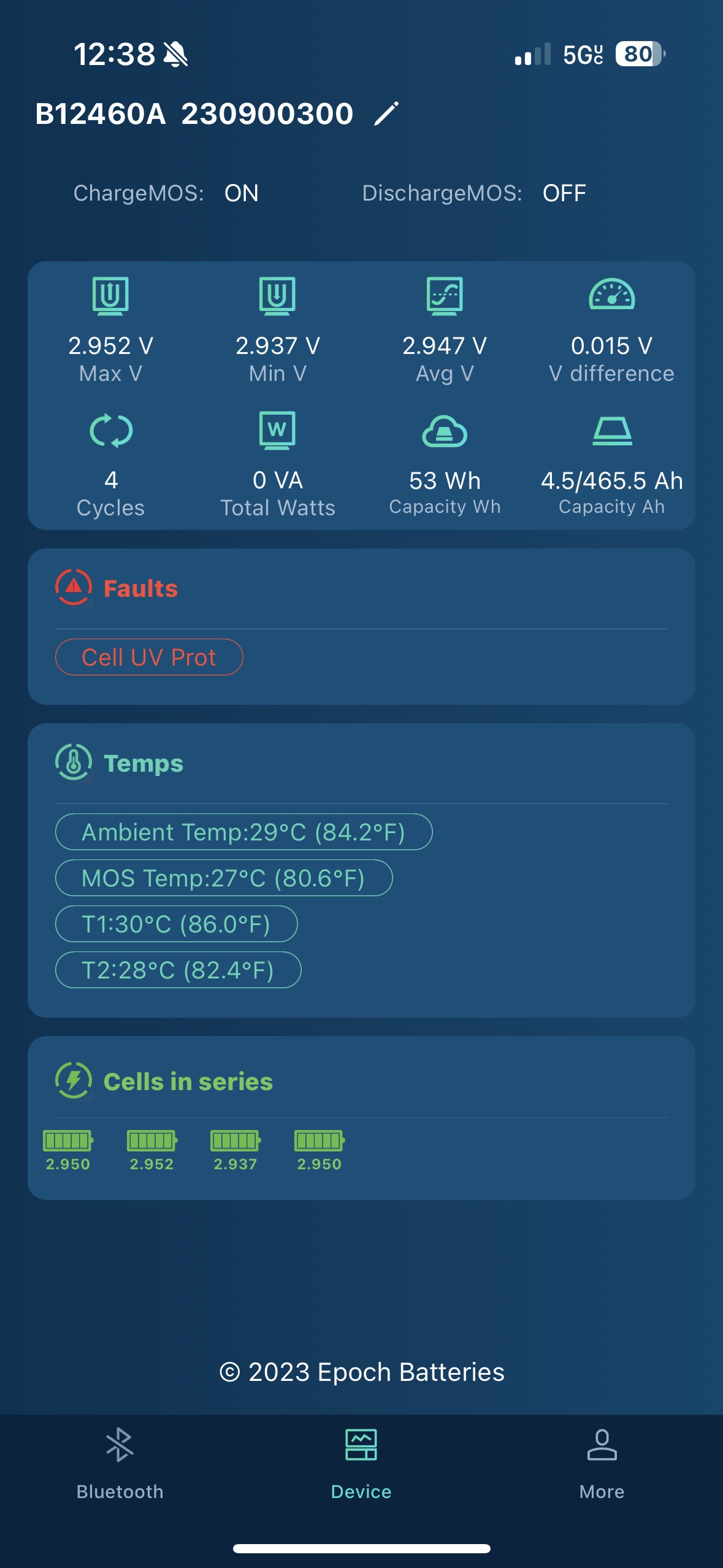
Bluetooth communications are also present and utilize the same app earlier Epoch batteries have used. The app provides the same detailed information and quick at-a-glance core health information. As I encountered with earlier batteries, the warnings and alarms the app displays are somewhat cryptic. I am fairly certain the DOC Alarm above indicates the discharge over-current alarm is active. I also triggered a COC Alarm which, I think, indicates charge over current. Because the label for both of those faults is in yellow, they’re warnings. The last screenshot shows a red fault for, I’m pretty sure, cell under voltage protection. That is a fault and has resulted in the BMS disabling discharge.
Victron integration opens many possibilities
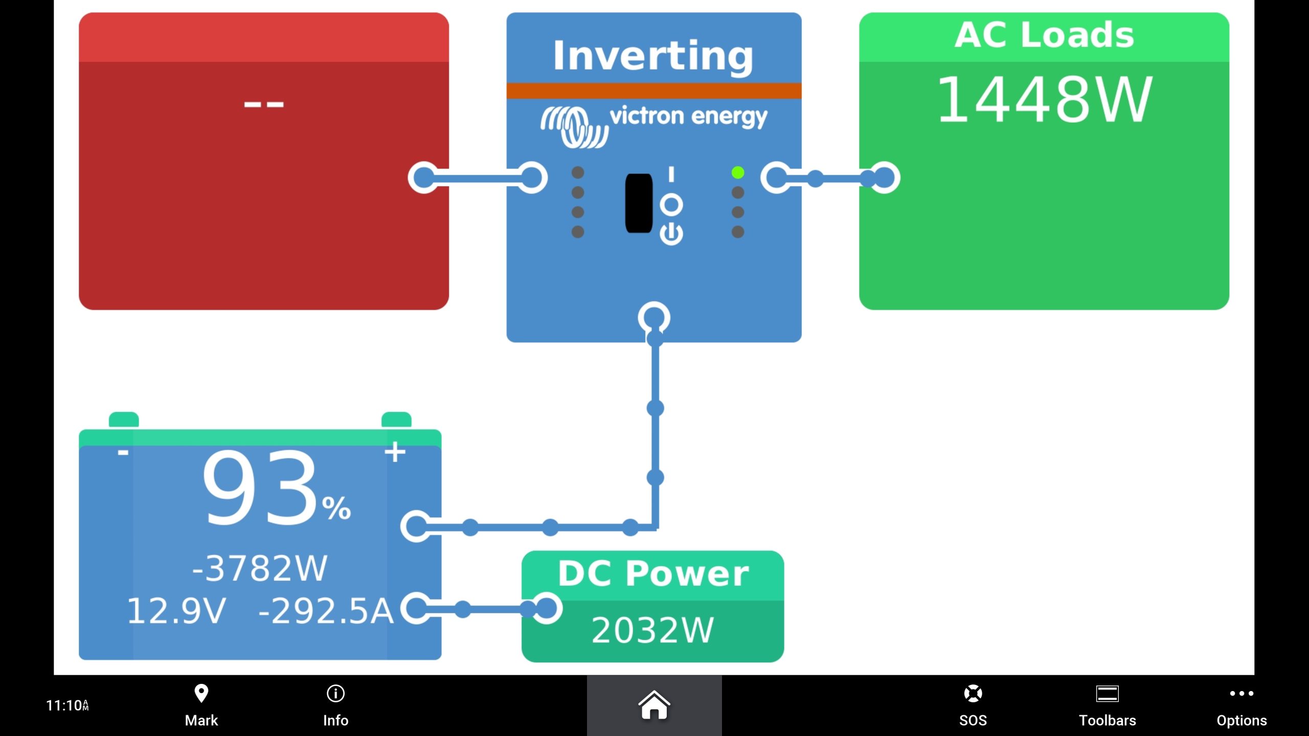
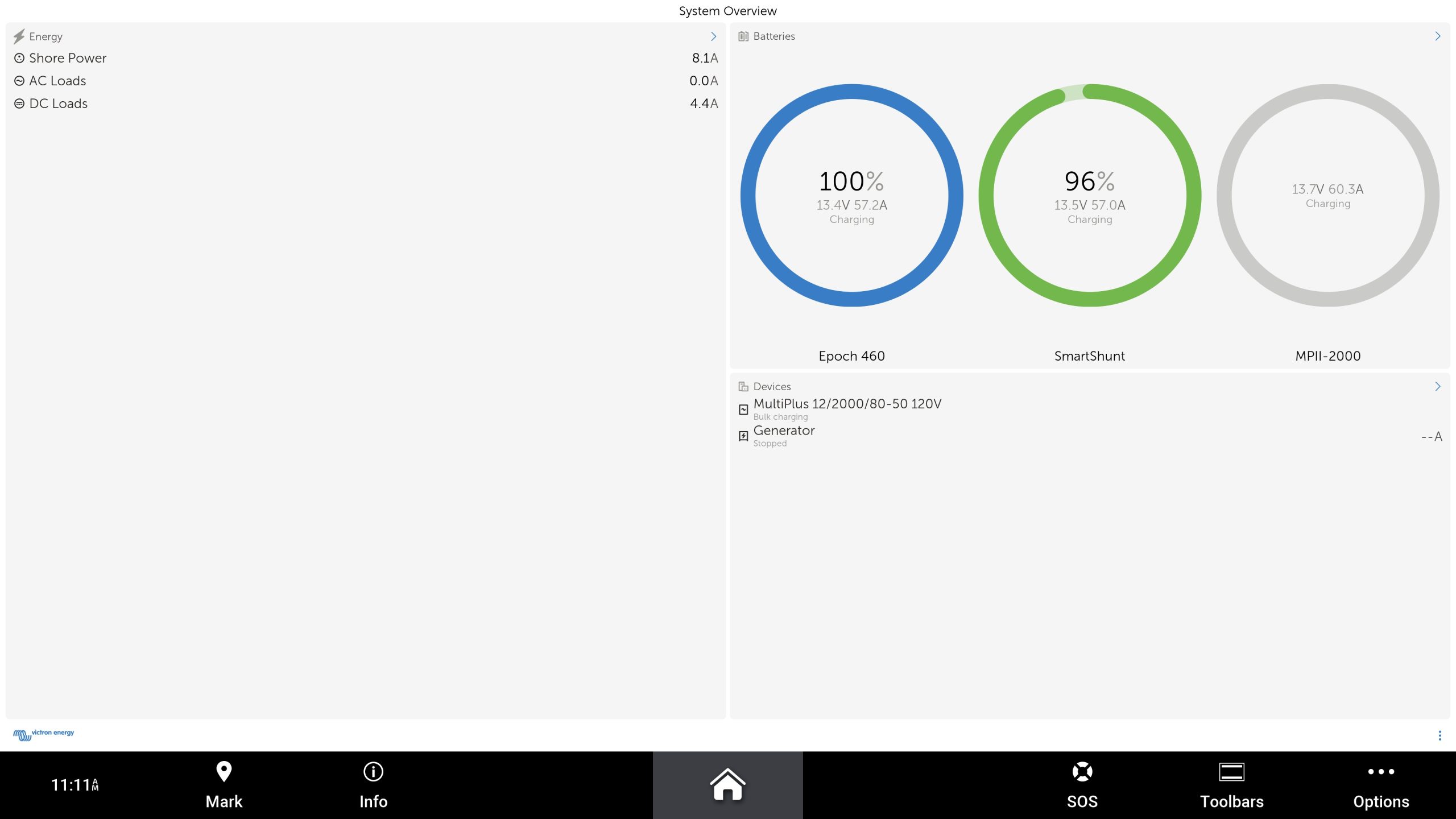
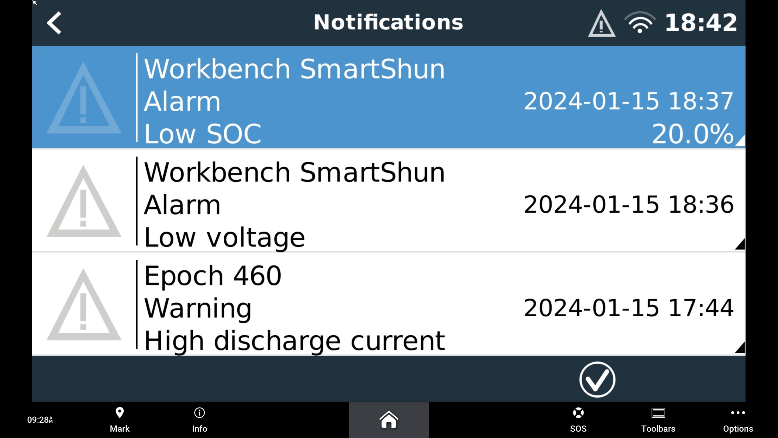
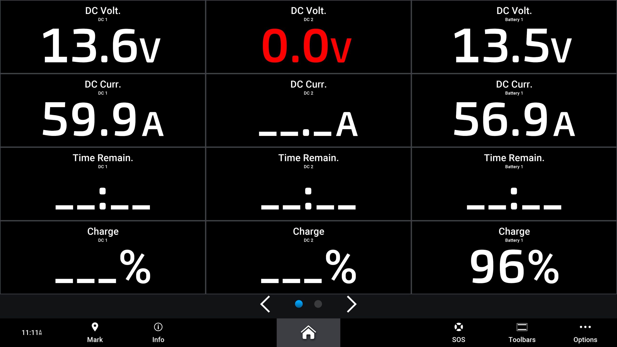
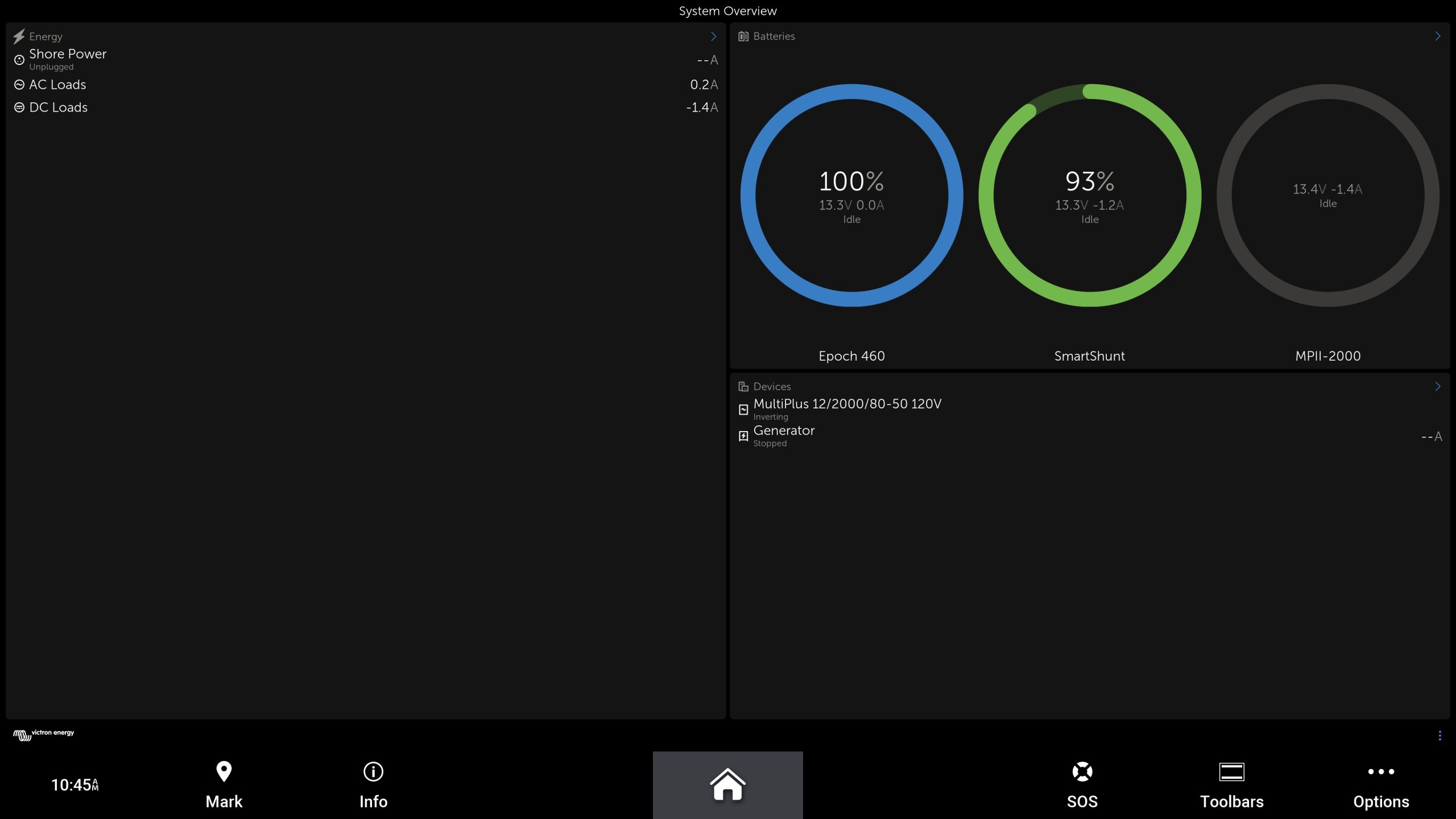
With battery data available and feeding to a Victron Venus OS device like the Cerbo, the boater has a wide-ranging choice of how to display the data. The screenshots above show several of those ways. The system overview and alarm screen use the HDMI output on the Cerbo and HDMI input on a Garmin 9219. With the display 9219 connected to the Cerbo, and a USB cable sending touch commands from the MFD to the Cerbo, you gain full display and control capabilities of the Cerbo. The second screenshot above shows Victron’s MFD app displayed on the 9219. The app leverages Garmin’s OneHelm app system to send data from the Cerbo via HTML5. Lastly, the final screenshot shows data displayed in Garmin’s native power view. This display is leveraging NMEA 2000 data delivered from the Cerbo to the MFD via Victron’s VE.CAN to NMEA 2000 cable.
Comparing available data
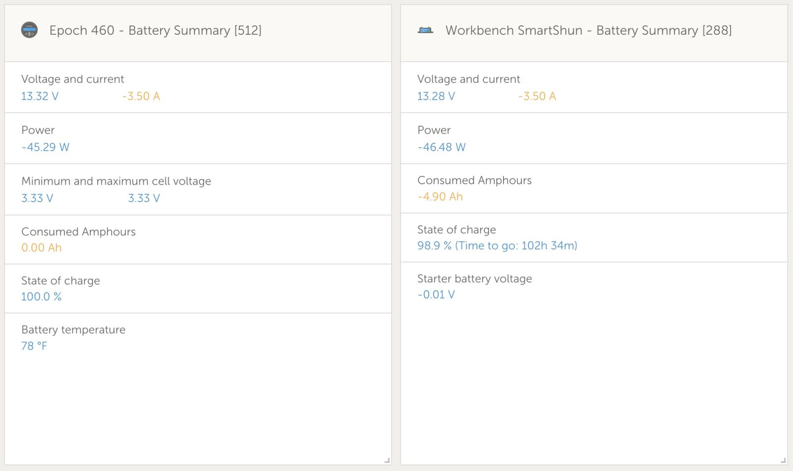
The two data boxes above compare data available via the battery’s BMS.CAN connection and via a Victron SmartShunt. The SmartShunt connects inline in the negative conductor to the battery. Both sources provide core data like voltage, current, and state of charge. But each source also provides data the other doesn’t. For example, the BMS.CAN connection from the BMS provides cell minimum and maximum voltages as well as battery temperature without an additional temperature sensor. Currently, the SmartShunt is providing runtime estimates and consumed amp hours the CAN connection isn’t. The lack of runtime data is under investigation by Epoch because they expect the battery should be providing it.
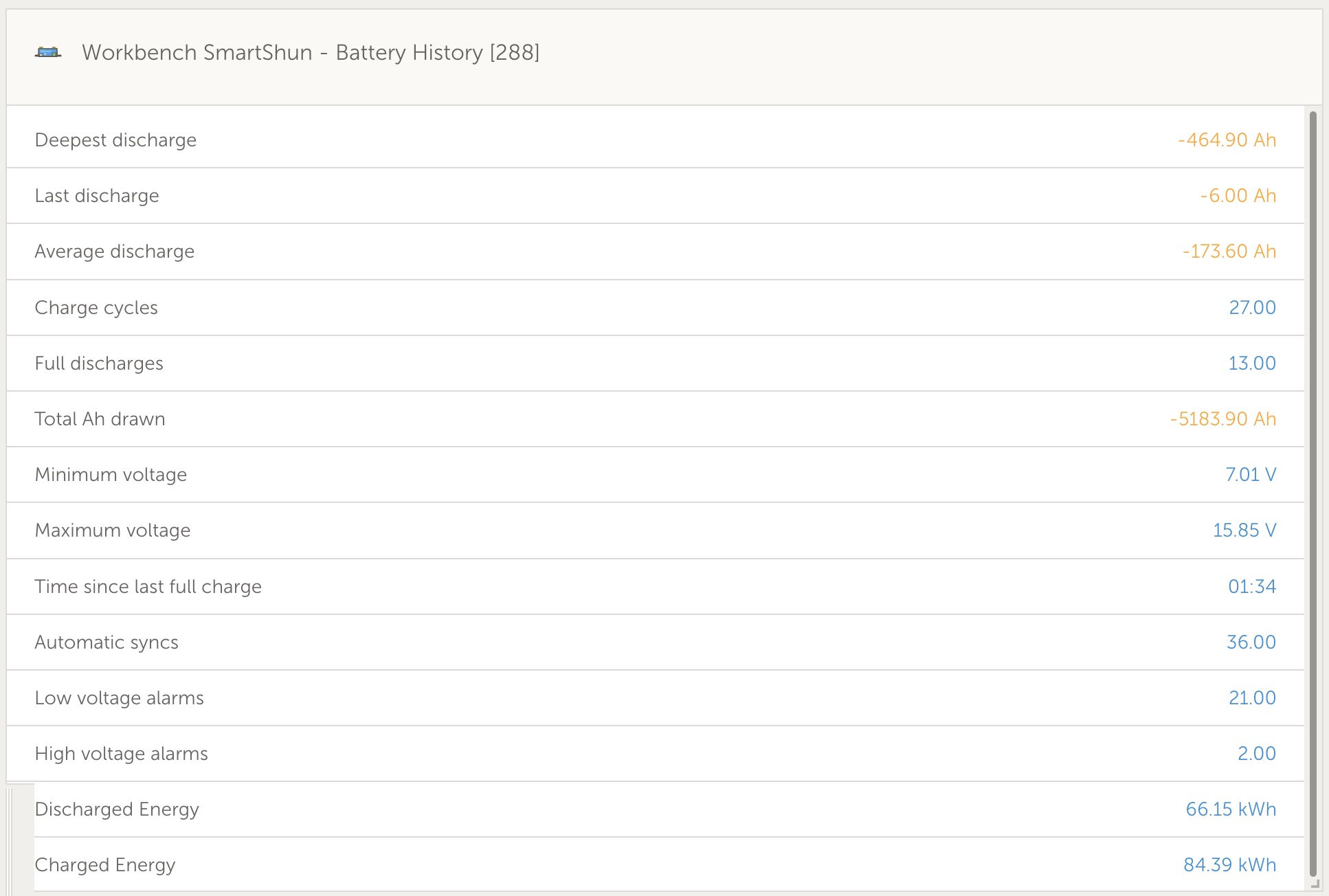
I greatly appreciate the Battery History information VRM and a SmartShunt or BMV provide. Via VRM, that information isn’t available leveraging the battery’s CAN connection. The Epoch app does provide a cycle count, but the detailed information on charged and discharged energy, time since last full charge, maximum and minimum voltages, and more are unique to Battery History. In light of the low cost of a SmartShunt, when I design systems I’m likely to still include one.
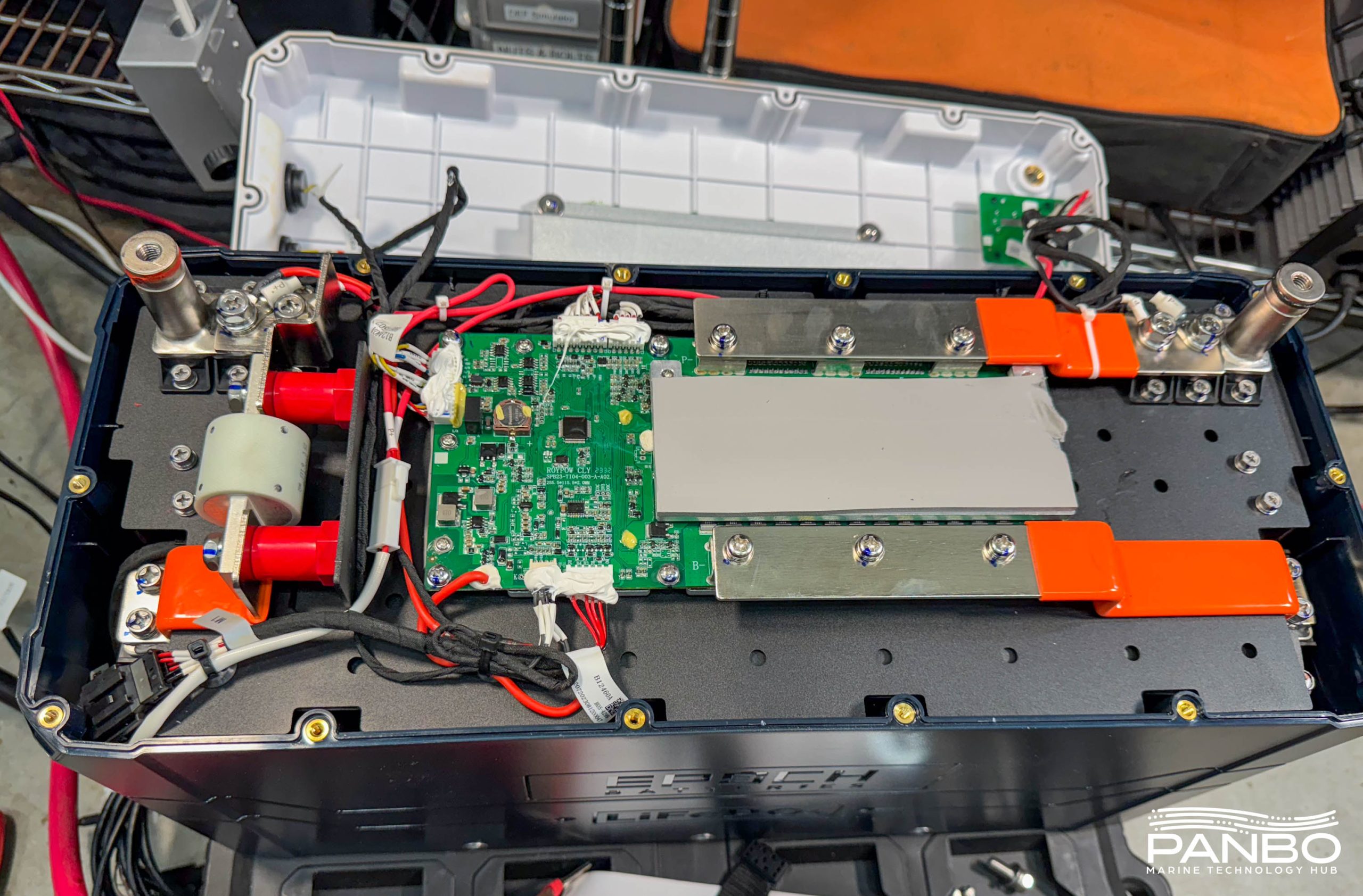
Teardown
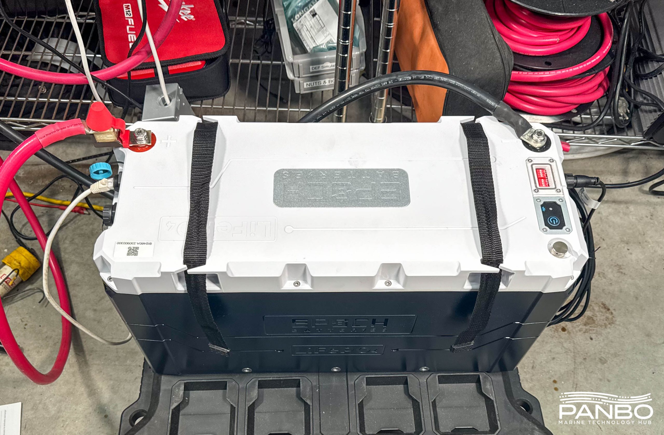
The construction of the Epoch 460 amp-hour battery is very similar to the 100 amp-hour battery. That includes a high-quality, water-resistant battery case. In the case of the 460, the top is secured by 14 hex head screws spaced around the top.
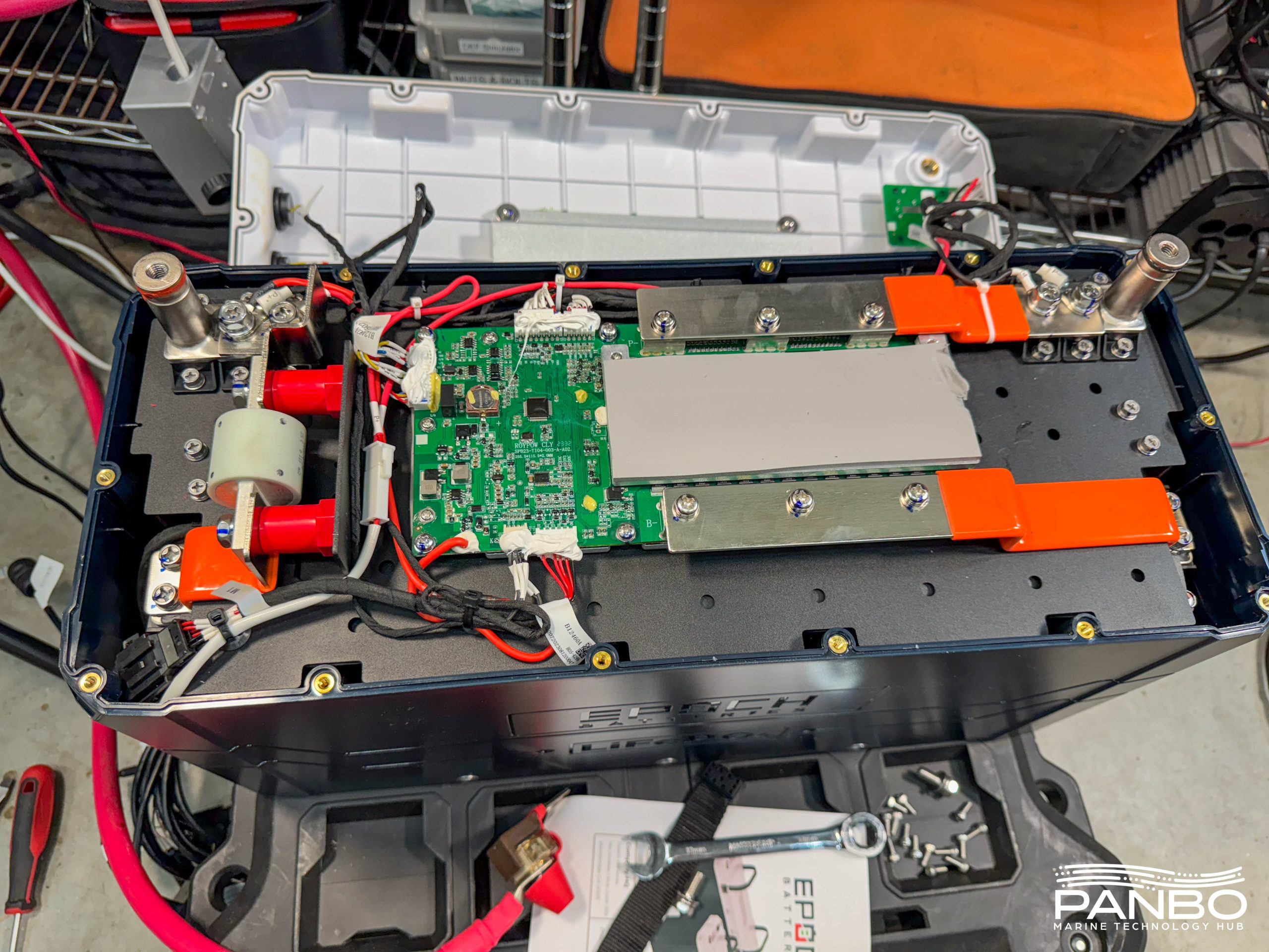
With the top screws removed, the top itself flips out of the way to reveal the BMS, bus bars, and aforementioned fuse. I’ve torn down a range of LiFePO4 batteries and Epoch’s batteries compare very favorably. The layout is clear and simple, the component quality is very high, and heck, there’s even a 500 amp class T fuse thrown in for good measure.
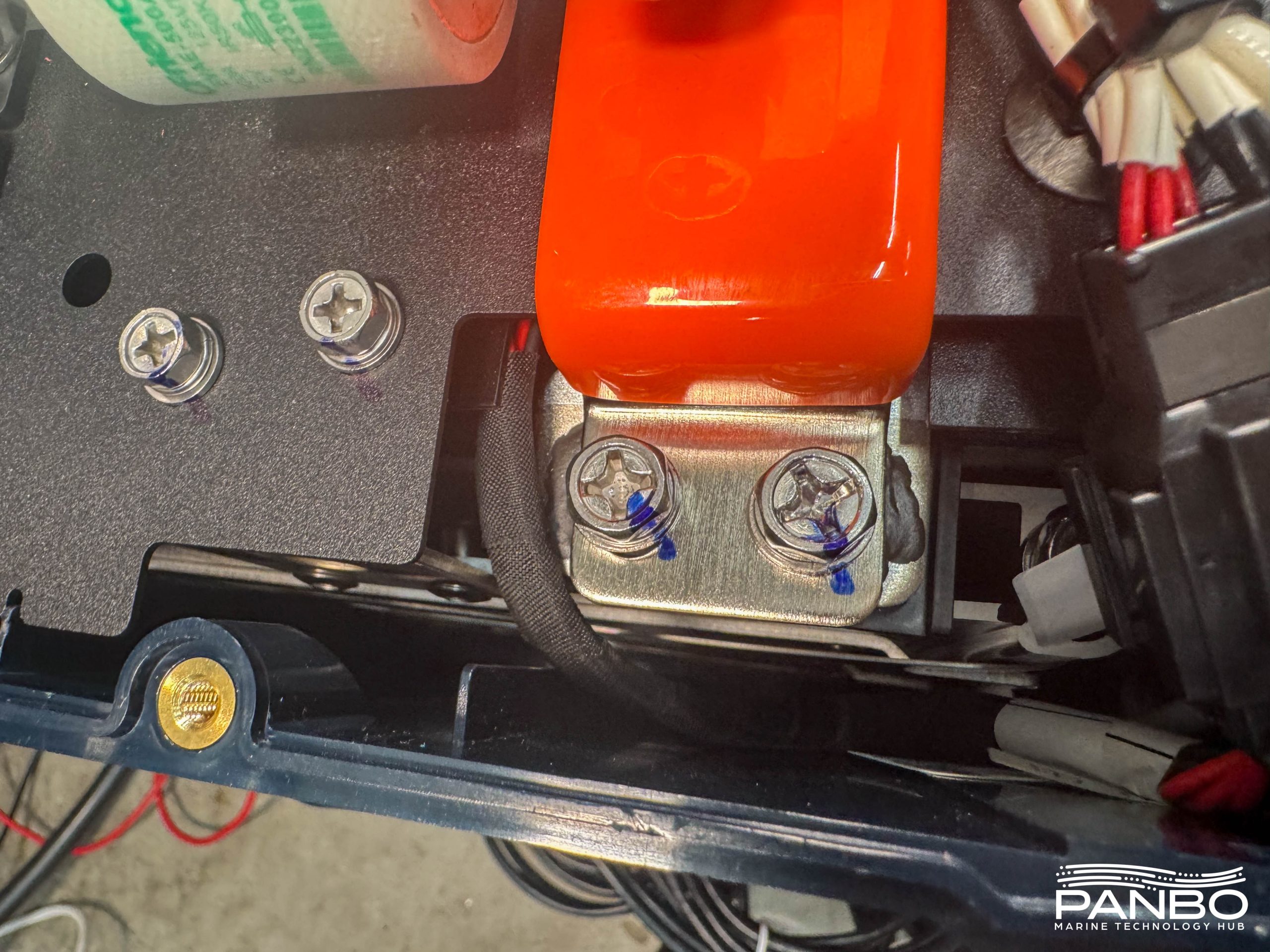
Every screw has a witness mark on it in permanent marker. These marks provide easy visual confirmation that the screws haven’t moved and are as they were at assembly. The marks on the screws securing the bus bar to the cell pack are fairly clear, but a little subtler are the marks top left above on the screws holding the top deck to the lower assembly.
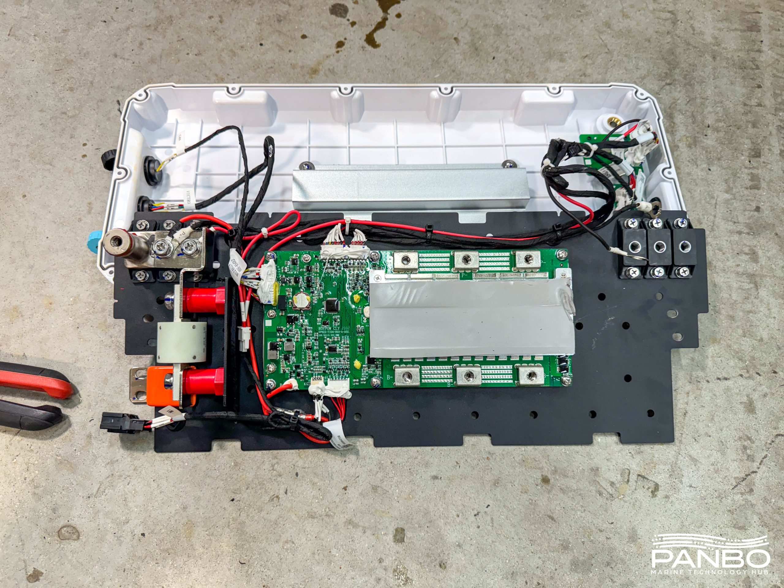
With the bus bars removed and the screws securing the upper half to the lower half, I removed the top altogether. That provides access to the cell pack which we will cover in a minute. But first, take a look at the block of thermal paste covering the FETs in the center of the image above. That paste provides a thermal pathway from the BMS’ FETs to the aluminum heatsink built into the cover. As we saw in the thermal image earlier, under heavy load, the heat sink does an efficient job removing heat from the FETs.
Cells
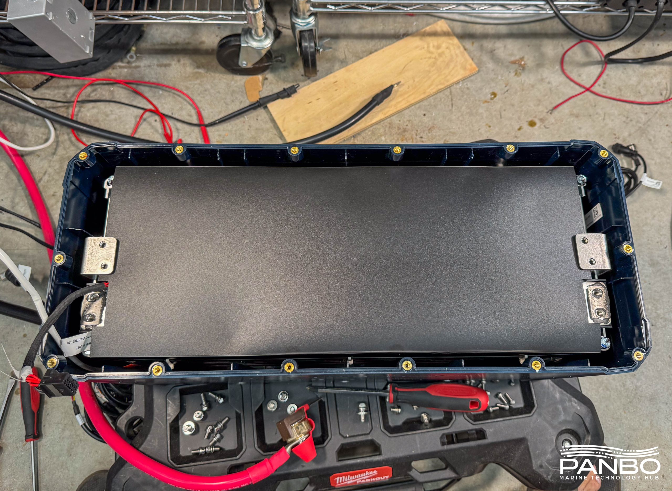
With the top half out of the way, we gain visibility to the cell pack below. One of the few complaints I had with the 100ah battery was the amount of wasted space in the case. The cells barely filled half the volume and left tons of empty space. That made the batteries pretty big compared to many other 100 amp hour batteries out there. There’s no such problem with the 460!
Though they’re hard to spot, there are four long bolts through the stiffeners holding the cell pack to the case. I assumed I would remove those bolts and pop the cell pack out of the case. You know what happens when you assume, right? I soon learned that in addition to the four bolts, an extremely effective adhesive holds the cells in place.
There’s nothing like seeing your shop in a video and realizing what a mess it is. I’m in the process of cleaning things up in here, but that’s another story. With the cells finally out of the case I was able to confirm the 460 seems to have the same high build quality. The aluminum stiffeners at the ends of the cells paired with tough metal strapping provide cell compression.
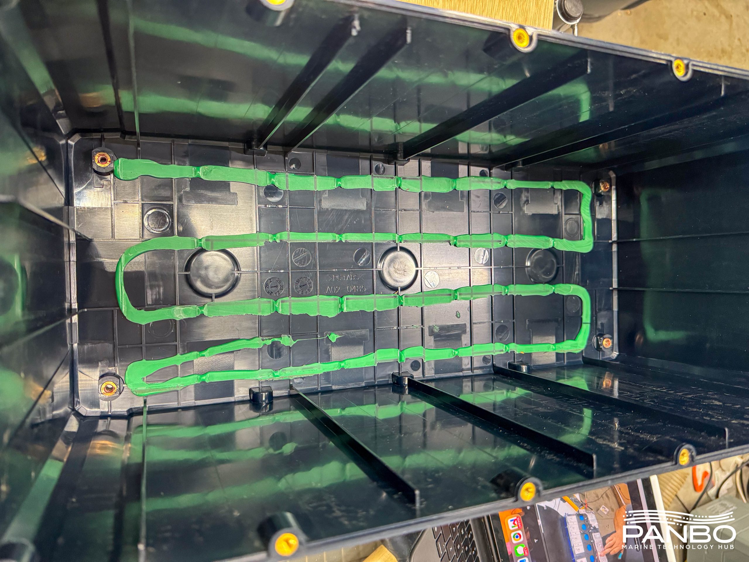
I’m not sure what the glue is that’s used to secure the cells to the case, but it holds extremely well. Especially considering the relatively small amount in the bottom of the case. Also, in addition to the glue, four long bolts secure through the stiffening plates at the end of the cells into the brass threaded inserts visible in the bottom of the case.
The cell QR codes are covered up by foam, but once I cut the foam away I found unobscured codes. The unobscured codes in the proper placement suggest these aren’t used or B-grade cells.
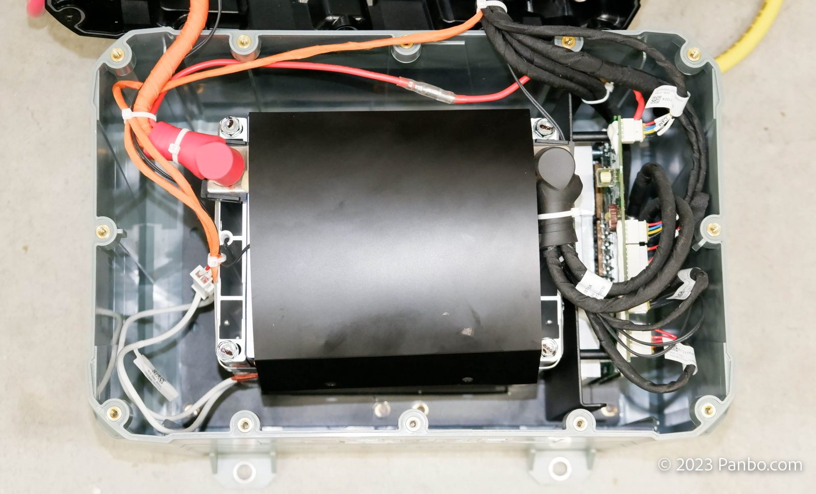
BMS
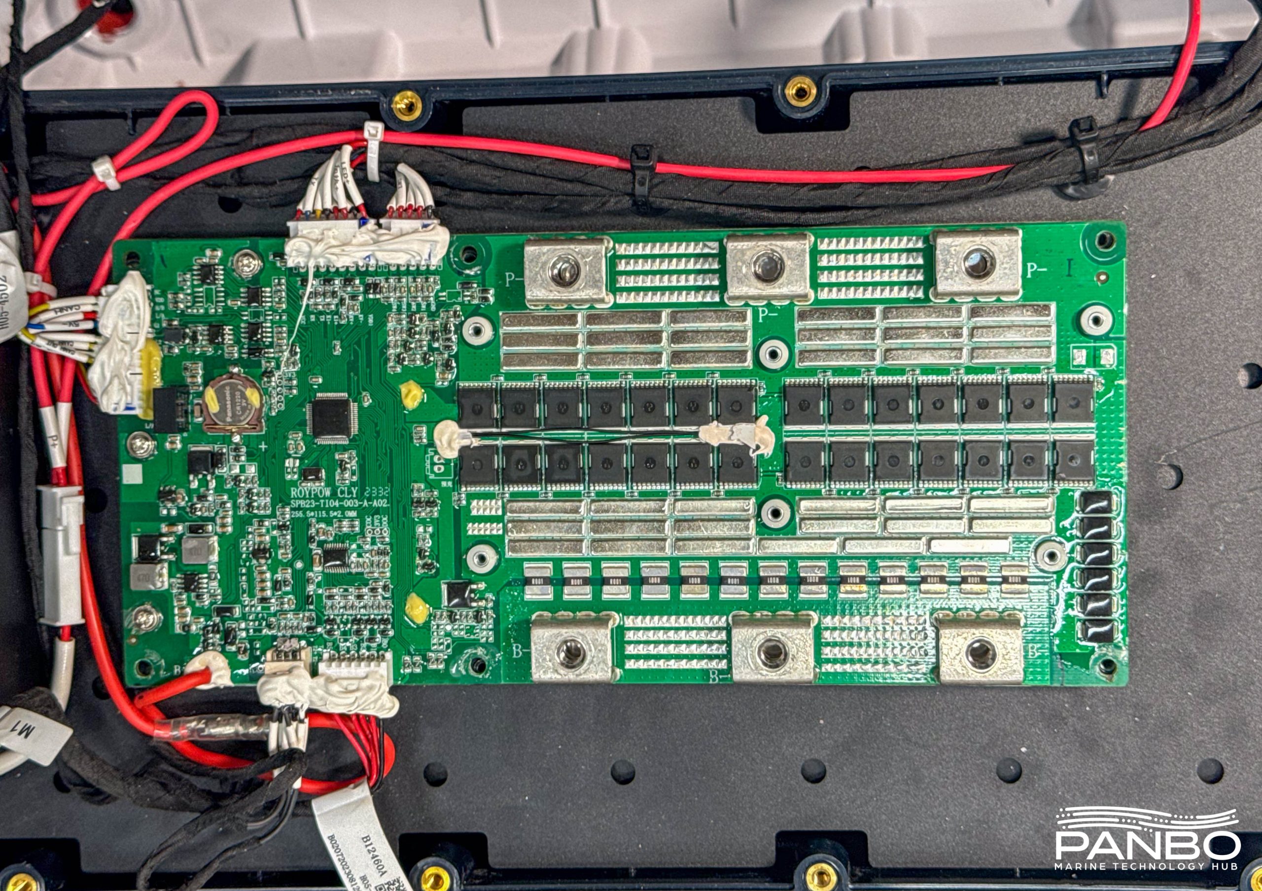
Up next I tore into the BMS to get a better look at the overall design and FET placement. There are a total of 56 FETs, 28 on the front and 28 on the rear. I believe half the FETs handle discharge loads and the other half handle charging duties. The board’s design appears robust and the components appear high quality. It’s also nice to see, like the 100 ah battery, the care taken with things like securing cables, insulation and jackets, labeling, and gluing all the connectors in place.
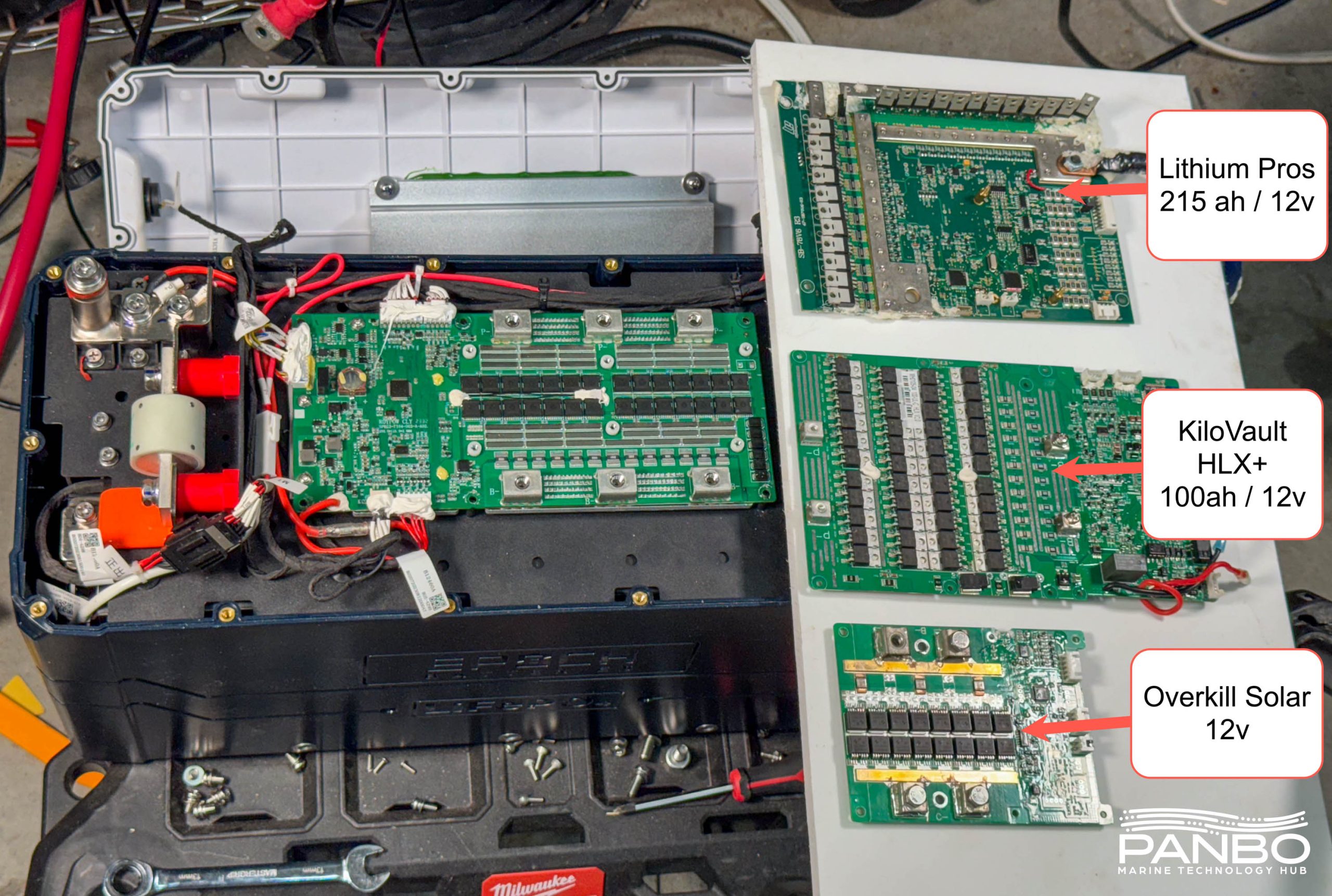
I’m not sure my traditional BMS comparison photo tells the full story. The current handling and durability of the FETs on this BMS appear to dwarf any others I’ve seen before.
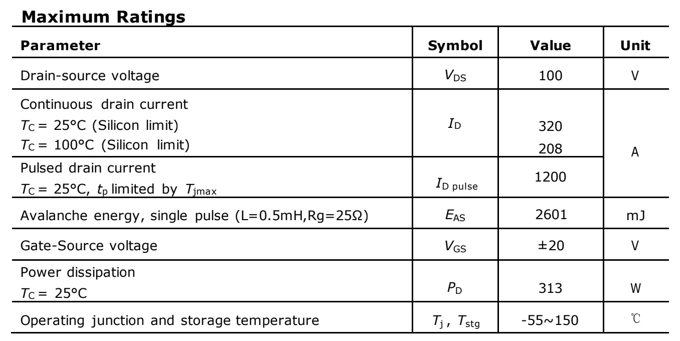
It appears from the spec-sheet that each FET carries a max rating of 320 amps and 100 volts. But, I don’t think there’s any way the traces on the board or the FET’s ability to dissipate heat could keep up with that amount of energy. It appears each FET can dissipate the heat from a maximum of 313 watts. I’ll be the first to admit I’m over my skis trying to interpret this data. So, if any readers have a better understanding, please chime in!
Familiar goodies
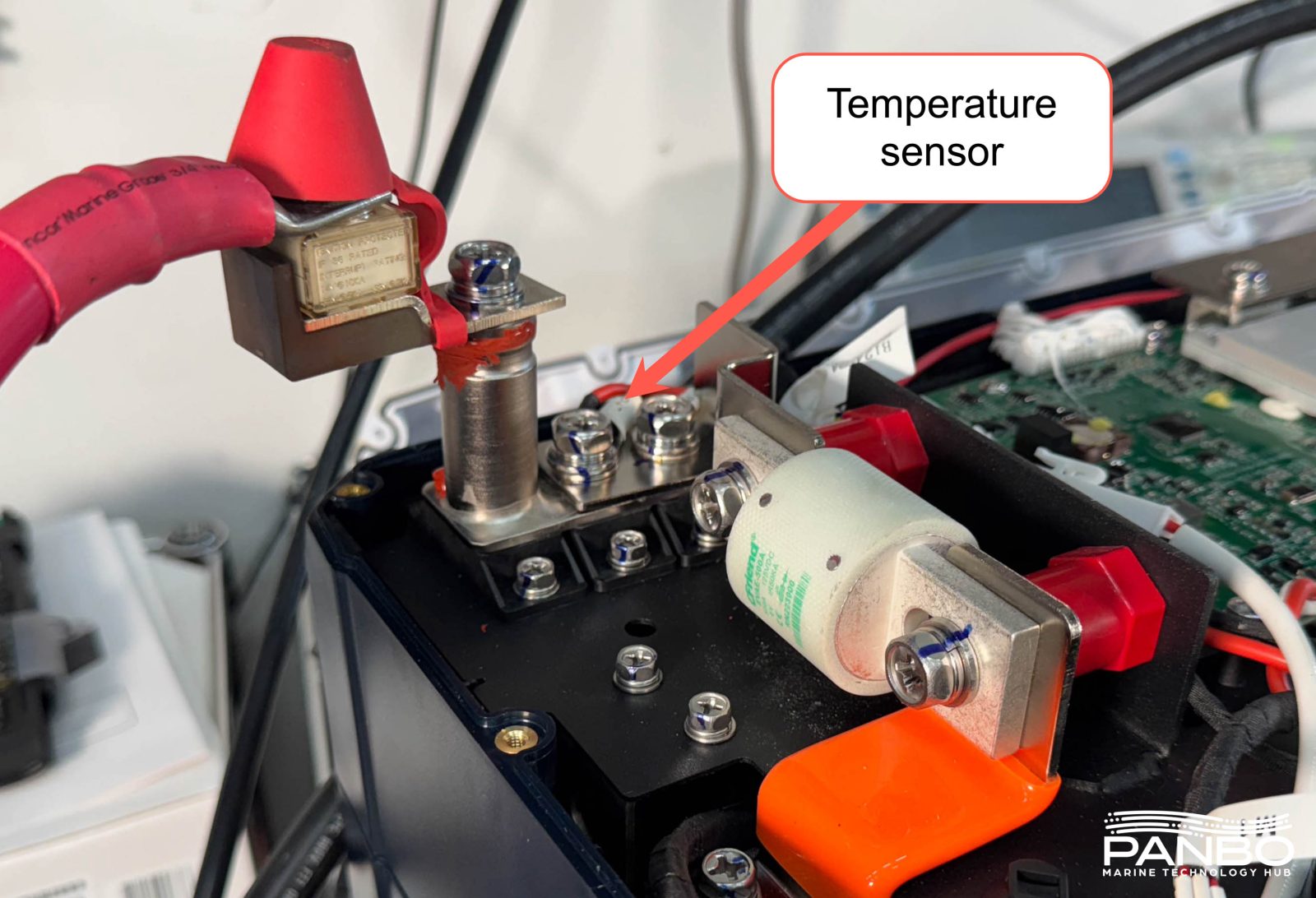
The 460 amp hour battery preserves many of the same features I appreciated in the 100 ah battery. Chief among those features are the temperature sensors on the positive and negative terminals of the battery. Prior to the 100 ah model, I’d never seen temperature sensors used like this. But once I did it seemed like such an obvious feature with so many benefits. I’ve seen the aftermath of a poor connection at a battery’s terminal. When you’re dealing with batteries that have the potential to deliver the current these do, the damage can be significant.

The app displays the temperature of both terminals, the temperature of the MOSFETs, and an ambient temp. I think that ambient temp is probably coming from the temperature sensor on top of the cells, but I don’t know that with certainty.
Documentation and ABYC-E13 compliance

ABYC’s E-13, the recently published safety standard for lithium batteries, spells out several requirements for compliance. In my entry on E-13, I noted that much of the standard relies on the battery manufacturer’s recommendations and requirements. Beyond extensive reliance on the battery’s manual, E-13 requires listing or approval from one of several agencies including UL, a BMS in place, and adequate water protection. There are several installation requirements and quite a few recommendations made in the notes.
So, for a battery to be able to be installed in an E-13 compliant manner, it must have a BMS, it or its cells must be approved, it must be protected from water, and the installation must follow the recommendations and requirements from the battery’s manual. The 460 meets the first three of these requirements but the current documentation doesn’t provide enough information to clear the last requirement. Several sections of E-13 reference information in the manual. In Epoch’s case, that information isn’t in the current manual. Epoch tells me they are near publishing updated literature that will provide all the required information.
Final thoughts
As I said at the beginning of this review, the Epoch 460 is one hell of a battery. It isn’t perfect and I’ve highlighted several of those imperfections. Most notably, I think the current sensing floor and data availability issues take some of the shine off the Victron communications. But, I still believe this battery provides pretty phenomenal value, safety, and performance. I would strongly recommend that if you’re going to install these batteries you add a Coloumb counting battery monitor.
I’m about to revamp the house bank on my RV and plan to leverage four 460/12s for that project. Currently, to my eye, these are the most compelling batteries available in the market. I’m excited to put a set to work and be able to report on their real-world performance.


Great article Ben. I appreciate it. I did a few testing videos and fount basically the same items. Especially the current sensing threshold. Luckily I already had a smartshunt. As a result I also think its a good idea to have one. In addition if there is ever a problem with comm cables or some other reason the Victron comms dont work you could quickly revert to using the shunt for charge and discharge control and info. Very happy with purchasing the pair of 460s for the boat.
Seeing how these go together further points to me liking them as an option. What I’m left wondering about these (and also the metal cased 300ah Epoch Essentials units) is whether orientation matters for installation. Do they have to be upright, or would they work fine laid on their sides or stood on end?
Info from Epoch is that any orientation except upside down is acceptable.
Good to know, thanks!
The OEM 500A fuse is available direct from Cfriend in China but expensive shipping or from AliExpress for around $35. Email me for info.
Has one major drawback – it’s made in China. That puts it out for me. Would be different if it was made in Taiwan.
Nearly 100% of the LiFePO4 cells on the market are made in China. You may be able to find a battery for which final assembly is outside of China, but at least the Cells will nearly certainly be made in China.
-Ben S.
I know that you reviewed installed and tested the Mastervolt MLI 12/5500 How does this stack up to that battery or the newer Mastervolt 12/6000? I know the former would cost more but wouldn’t the individual cell monitoring be worth it?… also a 460Ahr choice
Really looking forward to getting my hands on these in Australia. We have done alot of roypow installs. And roypow did say they build these batteries for epoch however the patent is owned by epoch so we won’t be seeing a roypow branded version any time soon
I looked for Epoch on Google Patents that i didn’t see anything, did Epoch say somewhere they have a patent on it? RoyPow makes a version of this battery case as well. If you Google RoyPow36v 100ah you’ll see the same enclosure. I’m guessing they just white labeled this size?
The 36v 100ah case from roypow is similar but different.
Roypow stated to me that they built the battery for epoch. Though epoch had a patent on the design “as in the technical design” I don’t know about the case. I’m not sure why you would bother putting a patent on that case . That said roypow said they wouldn’t be making their own version. I stead they have come out with a 400ah version using their case design from their 48v range
It’d be interesting to see the RoyPow version. Those guys build so many of the batteries everyone uses. I’m curious about the ability to patent a design for a battery! Never have heard of that. Thanks Moose!
Hi Ben, with regard to the FET specs, there are several things going on. First, they have these devices in parallel so they are sharing the load or charge current – while in an ideal world they would share it equally, in reality differences measured in micro- or pico- ohms will make a significant difference in how much current each device actually has to pass – so the devices are significantly over-rated for that reason. The 313 watt dissipation rating is dependent on being tied to a perfect heat sink at 25C, so in reality, they wouldn’t be able to dissipate that 313 watts for very long – and the same principle of some devices getting an unequal share applies – hence the significant over-spec.
This does bring up a question – do they really have two paths from the terminal to & from the cells, one for charge and one for discharge? If the discharge is on, does it prevent charging? (and vise-versa, of course 🙂 )
Hartley
S/V Atsa
Great info Hartley. All makes perfect sense. Your question about the sigle pathway to the cells got me thinking how the charge and discharge is controlled. From reading just now It appears many mosfets are unidirectional. So that makes sense too. Also…you can use the Roypow app to open and read the Epochs. In the Roypow app they give you the ability to turn off/on the charge and discharge mosfets with a toggle. Each side does in fact only control a single operation. I tested it several times. Pretty neat really. You can also engage the internal heater manually. One word about using non-Epoch apps. On a different battery with a JBD bms I tried the Overkill Solar bms app, which is not the oem app. It locked me out of that batteries bluetooth for some reason and I havent been able to get it working again. Even by disconnecting the bms and bluetooth module.
I was thinking the same thing about charge and discharge. Are they using diodes? I had a charger on a bat and at 13.5v the charge fets where off while the discharge fets were still on
They use a separate FETs for discharge and charge. For charging, you want to be able to turn off the FET in case of an error or if the battery pack is full. For discharge, you want to be able to turn the battery on/off and also to disable in case of an error. TI makes several battery monitoring BMS ICs that directly control the FETs.
As for MOSFETs, they block in one direction until you put a voltage on the gate. In the other direction, there is a body diode that conducts when the voltage is reversed.
While having perfect amp readings via the BMS can be useful, in practice paralleled LiFePO4’s will usually deliver differing amp flows due to variation in their internal resistance. While a common issue on low cost batteries, I’ve also noted this on a Victron battery system.. Having a battery monitor with shunt is therefore vital to monitor overall status of multi battery systems.
For me probably the biggest safety issue once fusing has been dealt with, is salt water flooding. To that end I do like a fully sealed LiFePO4 however the Epoch’s !P67 rating and construction quality looks good.
Would be interesting to know if a short circuit trips the BMS before the fuse blows? Could be a nuisance on a paralleled bank if it blew each battery’s fuse. Also from what I’ve seen the BMS and connections add considerable resistance so limit short circuit current such that external Class T fusing should be sufficient for most installations.
Finally thanks Ben for all your excellent work. I know these reviews must take huge hours to put together. Much appreciated 🙂
Typically, the BMS should detect short circuit conditions and turn off the FETs. However, if there is an issue with the BMS, then the FUSE is a last resort feature.
For now, the inclusion of an internal fuse on the battery does not automatically preclude requirements for class T fuses on the output of the battery. The AIC rating of MRBFs are only 10kA. I can’t find the let-thru current specs of the fuse they are using, but the let thru current of their fuse could easily be over 10kA (I could not find published data on the fuse they use). We will have to wait for the battery manufactures published specs to know for sure.
The article above stated its rated 50k
Here is a link to the fuse specs
https://www.hannovermesse.de/apollo/hannover_messe_2021/obs/Binary/A1089381/Fuse%20manual%201.pdf
ABYC standards only specify the AIC of the fuse. There’s no mention of a specific fuse type, form factor, etc in the standard. But, because they specify 20k amps for large banks and any size LiFePO4 bank, Class Ts have become the defacto standard as the only fuse typically used in marine applications that meets the requirement.
I’ve looked at the standard and tumbled it around in my head as well as discussed with several marine electricians. I can’t see anything in the standard that would require another high AIC fuse outside of the battery if the battery is equipped with one internally.
I think it’s worth noting that we’ve had a similar discussion previously about BMSes that interrupt the circuit in the event of over-current situations. Those discussions concluded that setup doesn’t meet the standard because in the event of a BMS malfunction, there’s nothing to provide a safety net.
-Ben S.
Thanks for the link. I have seen that data sheet. The problem is that they don’t define the let through current, so we don’t know what the short-circuit current is.
E-11.10.1.2.3.2 say that you need to have a fuse with an AIC rating of greater than 20kA if the AIC is greater than 10kA. Until we get the actual short-circuit current from EPOCH, we don’t know what type of fuse is required.
I think part of the confusion is that most people don’t understand how current limiting fuses work. Here is an article that explains what is going on.
https://www.eaton.com/content/dam/eaton/products/electrical-circuit-protection/fuses/solution-center/bus-ele-tech-lib-fuse-let-through-charts-current-limitations-charts.pdf
For what it is worth, MRBF, ANL, etc. fuses are not current limiting.
I don’t know, Andy – their wording is a bit different from what we are used to seeing, but it does sound a lot like AIC to me. “Breaking capacity: 50kA (125Vac, 220 VDC)…{with a 20 kA rating at higher voltages, which makes sense].
I would think that the ABYC was concerned that the fuse in question would interrupt the current flow, not what the peak current was before the fuse blew.
We all know that fuses are not instantaneous – if you subject them to a massive overload, they will conduct a greater-than-rated current for some (hopefully small!) amount of time, which is what you are talking about with your “current limiting” discussion. I doubt the ABYC is concerned with this at all, since all they spec is the maximum interruption rating.
If you have an MRBF or Mega and its interrupt is 6k, The Tfuse in the battery or batteries would blow well below the 6k needed to jump the gap in the Mega or MRBF, so as long as the class t is less than 6k amps (500amps in these) then AIC is achieved and a smaller fuse outside the battery is needed to correctly size for wire.
As for time – the mega or mrbf would blow quick enough to protect your wiring….. but if by chance a dead short that was big enough to exceed the AIC of the mega or MRBF, that amperage would immediately blow the class t. (it would have to be atleast 6k amps to allow current to flow…. then the time to blow with 6k amps on a 500 amp class t is pretty much instant)
The Epoch website is horrible. So far I get about 1/4 of a page to load. All the other links at the top do not do anything. I am glad their battery is better than their website.
Hmm, I have some complaints about the amount of information they make available, but I’ve never had any troubles getting the site to load.
-Ben S.
Don’t worry, like Ben says, what you find there won’t help that much–yet. (I have hope for them, but it’s a verify, then trust situation.)
Any idea what parameters the onboard BMS uses to determine a ‘charge cycle’? I just recently installed my 300-V2 battery. It came 50% discharged and it drained down to 43% before i had the time to install it. The charge cycle was at ‘1’ when i received the battery. After charging to 100% it still is at ‘1 cycle’. Does anyone know if it has to be discharged below a certain SOC before it registers a new cycle? Not that its an issue. Im more curious than anything.
Joe, Its quite surprising to see the rate of cycles as you rack them up. This is something we rarely ever kept track of with lead acid batteries and we typically used our gut and the calender to determine cycles..lol. on my golf cart I have been using lithium for quite a few years. On the Original Dakotas they were “dumb” batteries so I was again estimating. But since going with Epoch I have kept an eye on cycle count and what constitutes a cycle. I still dont know. Obviously there is an algorithm that compiles, I assume, voltage deltas high and low along side event of frequency counts and determines what constitutes a single cycle. When I discharge from 100% soc to 85% and then recharge it never registers a cycle. If I do that some number of times an additional cycle appears. If I do a deep discharge and full recharge a cycle count seems to appear. Paying attention to this has led me to several loose conclusions.
1) If a battery manufacturer where less than honest you could fudge cycle life counts in a manufacturers favor. But I would think there might be a standard for what counts as a single cycle. Not sure.
2) If #1 above gives an honest account of cycles, these batterries are going to last a very long time.
3) After monitoring how slowly cycle count rises in a battery that counts them and noticing it to be much lower than my perception expected…I never actually got the number of cycles I thought I was getting out of lead acid batterries..lol.
Victron Smart Lithium/Lynx Smart BMS has 2 different “cycle” start thresholds, depending if using DVCC or not. The default for DVCC is 70% and is configurable. Without DVCC, the monitor uses 65%. In either case, one has to meet 90% on the charge to log the cycle. With node-red, or manual monitoring, one can keep the cycle counter at 0 all winter long just by keeping above the cycle start threshold or stopping charging at 89%.
Some of you have seen my consternation with the Epoch manuals/documentation or forthcomingness of the marketing there. Understanding the system is, to me, a safety issue, but I come from a world where i get checkrides every 9 months and constant training. Many boaters don’t care, or need to know, but the information should be made available…
In the state of charge meters and the BMSs I’ve worked on, we define a cycle as the total percent that you charge a battery. For example, if you charge from 50% to 80%, that would be 0.3 cycles. After you do that a couple of times, you will get up to one full cycle. I’m sure other people do it other ways.
Interesting. Thanks for replies. That makes logical sense. I’ll have to keep an eye on it out of curiosity. The battery will calendar age into oblivion probably long before it hit the max cycles anyways.
I contacted Epoch because I think this is a great battery, but as an 8D is too big for easy installation on my boat. I suggested they make a similar battery with the same features – internal fuse, victron interface – in a 4D case. The capacity would surely be less, but I’d still buy it.
I know they are working on other sizes besides the 460. As I understand it, there isn’t anything to announce yet about additional sizes. Hopefully soon.
-Ben S.
Nice review. I still don’t think you have seen a class T fuse in a battery. Isn’t class T a UL classification? 😉
The fuse is IEC gR/EV rated and I believe it is a suitable substitute for the UL class T, but it is a faith based equivalence with just a little research on the IEC standards, and asking a few electricians and experts.
These seem like really good competition in the market place if they meet your use case. I wouldn’t want to be using a lot of power in a 12v system…24v and 48v make for more efficient systems, and the limitation of 4 batteries total in the configuration just makes the stored energy budget for overnight aircon, with no expansion potential. Still, it would be doable with some compromises (read: higher temp for less duty cycle)
I hope they send you one of the cranking batteries for review when they arrive. It is a promising spec for a use case I really want–starter/windlass (maybe bowthruster) AGM replacement.
Well, Jim, as Ben S noted above, the ABYC doesn’t require a “Class T” fuse, just one with an interruption rating above 20,000 amps. The factory spec for the fuse inside the Epoch battery says it will interrupt 50,000 amos, so it would seem to be sufficient to the task. The reason we’ve been discussing “Class T” fuses is that up until now, its the only one of the commonly-available fuses that meets the ABYC requirement.
Personally, if I was about to make the jump to LIFePO4, I’d be looking at this battery pretty hard. We made the shift with Victron two years ago, when the available selection was a bit more limited 😉 Now I’m thinking about getting another Victron 12V 330ah to buck up our reserve capacity.
Hartley
S/V Atsa
Not sure I said that a class T was required…just that he still hasn’t seen a class T fuse in the epoch or any other LFP battery—yet.
Class T is a UL classification and that really nice fuse in the epoch isn’t a UL class T fuse. Like you said, it doesn’t have to be. Possibly, the reason we have been referencing class T fuses is because that is the UL class and the “A” in ABYC references American standards.—the UL.
The IEC standard for the gR class covers semiconductor devices for short circuits and overcurrent protection. Because we are protecting the circuit, the logic seems to be that so long as the wiring outside the battery is fused to protect the external wires from overcurrent, it should be safe with the internal fuse interrupting for short circuit protection in the battery power circuit.
Like you, I’m considering adding more capacity to my Victron house bank. The introduction of the Epoch/Fogstar with the JBD BMS has increased the communicating LFP competition and I think that may be a part of the reason for the recent drop in smart lithium pricing. . I sure would have looked at the epoch, but I’m pretty sure I would have gone with the Victron. At today’s pricing, I am sure I would go with the Victron.
Re:Engine Starting – I note on the specifications on the battery that the maximum discharge is only 500A(30sec). Does that spec eliminate use of this battery in boats where the house battery is used for engine starting?
Hi Gary – unless your engine is really large (or hard to crank!) you’re not going to draw anything near 500amps starting it. The fraction-of-a-second inrush current when you turn the key might approach that, but the running amps will be less. Now if you have some 1000 HP beast, you might consider different starting battery 🙂
Hartley
It’s going to depend on the engine and the battery both. I occasionally start my 3GM30F Yanmar from the LFP bank consisting of 2 200 AH batteries each rated for 150 Amps continuous discharge. The engine roars to life and the batteries don’t seem to notice. If I wasn’t a belt and suspenders type, I’d probably ditch the start battery.
My boat has a 440Hp Yanmar (6LY2A-STP of 2002 vintage) configured to start from the house battery nominaly rated at 400Ahr (4x110Ahr Firefly). I am unaware of the start current but it starts very quickly. Going to primary start battery configuration would require electrical system rewiring, so I would want the manufacturer to confirm the battery use profile to include larger engine starting capabilities.
Gary, the starter for that engine is rated at 2.5 kW, so 200amps at 12 volts – or, more likely, 250 amps at 10 volts. I would suggest telling Epoch the starter rating to get an educated answer 🙂
so interesting
Roypow has just sent me their technical manual/specs on their new 400AH 12v battery that seems to utilize the same architecture in this epoch battery they build, albiet in a very different case. about the same weight .
@Moose.
Any information on the networking side of things?
so Victron canbus connectivity is included, it has 2 network ports “same as epoch” on the front along with dip switches. interestingly though it has 4 terminals. not to sure how i can post a photo into this forum.
maybe Ben would be able to ??
Edited by Ben S. to add a photo and link to the spec sheet
https://panbo.com/wp-content/uploads/2024/02/RoyPow400ahScreengrab-aPanbo.jpg
The PDF of the spec sheet is also available here.
Thanks Moose!
End edit
I have been watching roypow. They have their trolling motor line, but nothing comparable to the 460. Although they look identical.
So roypow is the manufacture of Epoch batteries, a rather massive company seemingly always at some interesting trade expo every week around the world.
they build the 460 for epoch, however Epoch holds the patents for it, so we wont see a roypow branded 460 any time soon it seems.
however they do have the same tech available in the 48v range, and their new 400 battery seems to be a 12v version of their 48v pack. depending on the type of install it looks like the roypow will hold its own , especially if wanting to run multiple packs “up to 4”
I am sure you have seen the Fogstar Drift series which is RoyPow, as well. : https://www.fogstar.co.uk/collections/drift-pro-lifepo4-leisure-batteries
I have no idea how different Epoch’s BMS is to the Fogstar’s semi-custom JBD, but i wouldn’t doubt that they are pretty close cousins.
On you question in the next post: if they are “press to connect” plug type connections (common in server rack systems), you might think about the risk of a disconnect due to vibration, jolts, etc…you know, the things that happen in a boat. There’s two of each so the cables can carry the current with reasonably sized cable (I doubt they are tinned), but many feel (self included) that the only reason to double current carrying cables is for voltage drop mitigation and each needs to be fused and capable of carrying the entire load/charge. 12V has consequences.
Very interested in hearing opinions on the battery terminal connectors with the rp battery
Im curious if you ran across this in your testing….
I have to set absorption no higher than 14.0v to get proper charging function. At the very end of the charging cycle I find that the Epoch BMS doesn’t balance cells well and one starts to run away from the others every time. To the point of getting a cell overvoltage warning. This has happened to 4 different batteries. 14v seems to be working just fine and lets me avoid the issue.
The bms on my batteries is shutting off @ 13.8 for me
Jason,
Your comment is timely. In the last few days it has become clear that what looked like a random anomaly might be a bit more of an issue.
During my testing, I saw a few high voltage alarms as the battery neared fully charged towards the end of the absorption cycle. In conversations with Epoch, it seemed the root of the issue might have been too short of a delay on tripping a high voltage alert. The theory at the time was that perhaps as charge acceptance tapered, the inverter momentarily allowed voltage to climb and with a very short trip delay, it was generating an alarm.
Throughout my review, and continuing as we investigate what’s happening, I have been in touch with Andre, co-owner of The Yacht Rigger who recently completed an impressive install including four 460s. They also observed the high voltage alarming and decided to disconnect Victron comms in order to avoid the nuisance alerts for the boat owners. For quite a while, that seemed to be a good solution until the end of last week when the boat experienced more unusual behavior. That behavior included signs of voltage fluctuation, like intensity changes in lighting, and ultimately a fault condition that left the boat without house power.
I spent most of the day in Tampa with The Yacht Rigger visiting the boat and trying to understand what’s happening. We had a tool that is supposed to connect to the BMS’ CANBus interface and allow detailed visibility into the batteries’ operation. Unfortunately, the tool wasn’t working so we are waiting for new units. As soon as those are received we will carefully monitor the behavior of the batteries on this boat as well as my test battery and see what we can figure out about what’s happening.
The unusual part of the behavior is that it seems there is something triggering a range of Victron inverters to poorly regulate charge voltage towards the end of the charge cycle. We don’t understand this behavior yet but hope to have more clarity once we have better visibility into the BMS’ operation and parameters.
I will update this thread once I have more information. In the meantime, if others have any information from their own experience, please feel free to share it here.
-Ben S.
good to hear im not alone. That means hopefully this will get resolved by Epoch eventually.
To be more clear….
This issue has happened on two 460 units and two of the 300ah essentials units.
I had to also disconnect the Victron comms as it caused an alarm often.
So far it seems 14.0v absorption and 13.6v float is working without alarms with the Victron comms disconnected. Though now I will certainly run through a few more cycles to see if this remains ok.
On the 300ah units I had to set absorption to 13.8 or 13.9 to stop this from happening and preventing a cell to run away from the others.
My bluetooth app also only works sometimes for the 460 units. It will always show state of charge and overall voltage but not always cell voltage info. And sometimes it shows all faults for a few seconds even though the battery seems to be functioning fine.
Equipment is fully Victron aside from the batteries.
It took a lot longer than I would have liked, but here’s a video showing the full charge protection function in action.
https://youtu.be/yPFaH-b1b0Y
It seems like there are probably two factors causing the charge MOSFETS to close. First, the full charge protection feature I covered in this video. The second issue I think is impacting the batteries is cell balance at top charge. My working theory right now is that the passive balancer on the BMS can’t keep up with any large imbalance of the cells. I believe the passive balancer is capable of only 1 amp or less balance current. If that’s the case, that’s a very small adjustment against 460 amp hour cell pairs. More investigation is underway on that and I’ll report back when I know more.
-Ben S.
Precisely. I think I’m estimating 1-1.4
When I get around 2. 5 amps or less going in on a balance charge… I was able to achieve 14.0 anything more and I’d get OV. That’s how I started recommending that charge spec for balancing.
Bench top charger is great for this.
During my reading on these topics it seems that most, if not all Victron capable batteries sometimes have these same issues. One of the most used Victron capable batteries in use is the Pylontech. They are widely in use and have a several year head start on Epoch but in a non-marine capacity for off grid systems typically run at 48 volts. If you google search “Victron Pylontech over voltage” you will get tons of hits on this topic. Of course there is no guarantee these issues are exactly the same I feel like they are likely very similar. If you go to the Victron page detailing Pylontech information you can read through quite a bit of similar troubles and ways to remedy. Keep in mind Pylontech and others have these issues and they were actually “certified” by Victron back when Victron tested these things. You can see that info here https://www.victronenergy.com/live/battery_compatibility:pylontech_phantom#my_system_only_charges_the_battery_to_52v
There is potentially a few nuggets that may be applicable there. In addition I would like to ask if all of the people having these issues are running solar? There is also a train of thought in many discussions that both cell overvolt and battery overvolt may be cause by sudden spike in solar output for various reasons. That may also explain flickering lights and other anomalies. But this issue seems to have been around for a while and is pretty difficult to penetrate.
In the mean time people seem to just turn down the voltage on the DVCC. However some are reporting
Ben, when the power shut down and vessel went dark did the Epoch discharge mosfets shut down when the Victron comms were disconnected?
Jason, you said you set absorption to 14.0? Are you not using Victron comms to a Multiplus or other Victron charger? If not and you are using your lithium settings, you may double check all of your settings. If you are using the Victron cable from the Epoch to a Victron Multiplus or other capable charger then I believe absorption settings along with mos other settings are not in play.
Mathew, when you say your BMS is shutting off, are you also using a Multiplus and Victron equipment? When checking the app in this condition are both the charge and discharge mosfets off or just charge mosfets turning off?
Thanks for the feedback and I will be following to continue to learn.
This is probably a red herring, but it is easy to check… I’ve seen issues with DVCC and over voltage in other Victron configurations (no lithium) when the GX device driving the DVCC gets overloaded and slow to respond. Being overloaded will typically show up as big spikes in the d-bus round trip time metric available in the VRM graphs.
Yes when the Victron Comms cable from Epoch is connected it feeds the cerbo all the info about settings it needs. However, it became clear that this just doesnt work correctly. Alarms often about overvoltage coming from the battery to the Cerbo.
After that I disconnected the epoch cable and put in the settings manually as I usually would do. They are correct. Well…besides having to use a lower absorption and float of course.
This issue happens regardless of charge source for me. It happens on Victron solar controller, Multiplus 3000 shore power and Victron IP65 charger.
The same behavior occurred when charging the EPOCH 460 with the Zeus voltage regulator and a Balmar AT-165.
I won’t be able to test again until after the 15th.
What charge settings were you using for the the Zeus? So far in my experimenting I’m planning on a max charge voltage of 13.8.
If I recall corrrectly, I was using 14.2 bulk and 13.6 float. I’ll be back in the shop next week and will confirm.
Has anyone seen different firmware versions with the batteries. I’m seeing version 15 and 16. I emailed epoch about what the current version is and how to update, have heard nothing back
I have successfully balanced a few of these now.
First make sure your cables and everything are equal… equal torque and proper installation.
It helps if when you do your initial charge you use a bench top charger so you can monitor tail voltage and evenly get the battery properly charged for the first time.
If you have installed and only see voltages of 13.4 5 or 6 then the following will get you there.
Bring batts to below 13.3 for the highest cell. Switch inverter to invert only if you have to… and run her down. You can view it in the details section of the batteries on the Cerbo/Ekrano or app. You can do all this remotely if you need to.
Charge at 5 amps up to 13.6 then reduce the tail voltage- charging till you get alarm. Drop again. 13.2/13.3 …going that low turns off the restriction on charging. Charge up to 13.7 and hold, drop amperage to the lowest possible after house loads keeping in mind the bms will not see amperage below 1.3 amps. Use this small tail voltage to slowly bring voltage up to 13.8 then 13.9 by changing the dvcc volatge setting one tenth of a volt at a time letting batteries sit and slowly even out. Keeping the amperage as low as you can bring the voltage up .1 at a time. When you get to 13.9 go 13.95 go until you get an alarm. Repeat the whole process again. Eventually you will be seeing 14.0/14.1 usually in just a couple cycles.
I set float at 13.4 and abs 14.0 or 14.1.
Jake. Thanks for the great info and good experimentation. It makes sense. I saw these 460 owners having these issues and was wondering if I maybe I missed something on my bench testing since I wasnt having these issues prior to tearing down the bench set up. I was having them on the first 2 or 3 cycles though. But from what you are saying, and if you are correct, it seems I did something similar pretty much on accident during my bench tests. The parameters were not identical and I also discharged MUCH deeper just for testing purposes but the result may have been the same. I took the pair of 460s down to low voltage cut off or 11.1 volts and the discharge mosfets shut down output. I then charged at approximately .05c from 0% to 100% (100% was 14.2 as set in DVCC) and had no issues. I did other discharges and subsequent charges without issue as well. I am thinking this discharge and slow charge served to balance everything much closer and I never had a stray cell after this. This also seems to mirror what the guys with Pylontech batteries have seen. Just by chance I actually made a video of this portion. Ill post it below.
I think there may be another separate issue that occurs on some boats with solar regarding poorly controlled voltage and spikes, which is a Victron issue. Unfortunately this is something I have only read about so I havent tested.
Again, thanks to all for the discussion since I am still soaking up this info on best practices. Much appreciated.
https://youtu.be/oUcjefQ8TAU?si=gZVVy1d2B3PAyA8S
I think there might be some confusion about what’s happening and quite possibly more than one scenario being experienced. The issue I described above is not, I believe, caused by cell balance issues. Instead, it’s caused by the BMS turning off the charge FETs being disabled when the battery reaches 100% SOC according to the BMS. I have a video I’ll get published tomorrow that shows this occurring. As the battery reaches 100%, the Charge MOS status in the app transitions from on to off. At the same time, you can clearly see that none of the cells are out of range nor is the total battery voltage too high.
Here are two screenshots showing immediately before and after the disconnect event.
Epoch has confirmed this is done to protect the cells from overvoltage. But, disconnecting the batteries from their charge source is problematic in many systems. I think the high voltage alarms we are seeing are the result of the inverter being unable to stabilize its charge voltage without a battery connected.
I’m waiting to have some additional conversations with Epoch about this approach to protecting the battery. I understand what they’re trying to protect against: continuous high-voltage charging damaging the cells while still staying below disconnect thresholds. But, I think this approach is problematic. I believe this behavior has been used in other Epoch batteries as well as by quite a few other LiFePO4 brands.
More to come as I learn it.
-Ben S.
Ben, In the first screen shot it shows the charge mosfets on but only pulling 3.5 amps
How many amps were available for charging? Or were you just charging with 3.5A?
I was charging from a MutliPlus II with 80 amps of charging available. The battery was only accepting 3.5 amps as it was at the very tail end of its charge.
-Ben S.
Note the battery is accepting 3.5 amps if the charge MF is off. That is likely not an accurate reading.
Forgive me if I am off base or misunderstanding. I think we are all trying to wrap our head around things..lol. Myself included. The following is just thinking out loud and NOT making statements of fact.
If you were down to 3.5 amps going into the battery but had 80 amps available that would seem to imply the battery is full full. It would make sense that the battery detected this and shut down the charge mosfet. The voltage of 14.23 (an individual cell voltage of 3.55-3.60) is IMO very high. From all the research I have seen, when doing capacity tests of either individual cells or battery packs the capacity testing at various charge voltages seemed to imply anything close to 3.50 was full full full and 3.45 was 98 to 99% full. 3.65 or 14.6 from everything I have seen is extreme.
So in the operation of your system when you saw these shut downs, what was the max voltage setting in the DVCC? If it was set above 14.2 it seems the Epochs primary protections may act independently from Victron communications shutting down the charge mosfets due to an alignment issue between Victron Protocol and Epoch primary safeties. IMO all the primary protections inside an Epoch are probably active and completely independent of what that same Epochs Victron protocols are saying to a Victron system. If during operation (charging and discharging) as per Victron commands, one of those Epoch primary protections is exceeded, the battery will still act on those appropriately. I think the key is to ensure that the operating envelope of the Epoch/Victron system, when guided by the Victron protocol, never exceeds or comes close to any of the primary protections of the Epoch. In order to do that I think several things have to happen.
1) cycle the battery as Jake Archer suggested. I think the need for this is a result of very large capacity cells. This IMO stands to reason. Initial Cell balance over a capacity range of 460ah is likely far more difficult than cell balance of one that is 30ah or 100ah. And it stands to reason it may take more cycles to align things.
2) With DVCC enabled the max charge voltage must be set much lower than most people may think is correct. The community with the most experience with Victron Comms and nuisance tripping and warnings seems to be the Pylontech community. Its shocking how low the voltage Victron suggests to operate Pylontech batteries. The following is from the Victron site in their Q&A discussing system stability of Pylontech batts with Victron systems:
Q: “My system only charges the battery to 52.4V
A: When DVCC is enabled, the battery (via the CAN-bms) is responsible for the charge voltage. The Pylontech battery requests a charge voltage of 53.2V. We have however found that in practice this is too high.
The Pylontech battery has 15 cells in series, so 53.2V equates to 3.55V per cell. This is very highly charged and makes the system prone to go overvoltage.
It should also be noted that a LiFePO4 cell stores very little additional energy above 3.45V.
For this reason we opted to override the BMS and cap the voltage at 52.4V. This sacrifices almost none of the capacity and greatly improves the stability of the system.”
Extrapolating from the above numbers the above statement from Victron suggest charging a battery system to 14.2 (3.55) is ” very highly charged and makes the system prone to go overvoltage.” and they recommend using a more stable 13.96(3.49). It also almost sounds like Victron systems knows when a Pylontech battery is hooked up and Victron has overridden Pylontechs own upper charge limit for a more stable and lesser voltage. I assume this was done when Victron used to test and “certify” third party batteries, which has not been done with Epoch. Apparently Victron doesn’t do this any longer. So It would appear we (Epoch Users) will be responsible to find this more appropriate and stable upper charge voltage.
I have heard from several others that did a bunch of cycling on the 460s and ended up ok using anything from 13.8 to 14.0 with much greater stability. I did get mine to cycle with DVCC max voltage set to 14.2 ok but will likely adopt the 13.96, give or take a tenth, when the system is actually turned on after install.
I apologize if I am completely misunderstanding the issues. I think there are likely other anomalies as well that deal with solar or other systems.
Alan,
I think there are several factors you aren’t taking into account.
First, let’s talk about charge voltage. Epoch calls for a bulk voltage of 14.2 volts as listed in their spec sheet: https://cdn.shopify.com/s/files/1/0251/0484/2798/files/Epoch_B12460A_Data_Sheet.pdf?v=1701937833. They also call out a maximum charge voltage of 14.6 volts. You are correct that bringing the cells above roughly 3.5 volts each is going to result in minor differences in SOC.
For my investigation into the problems we have been seeing, I have disconnected Victron comms from the battery and used a 14.2 bulk / absoprtion with float set to 13.6.
But, what you might not be accounting for is balancing. Most BMS will balance at top charge once voltage reaches 14 volts. If the battery isn’t charged above 14 volts, the BMS won’t have an opportunity to balance them. In my mind, this is another reason that disconnecting at 100% SOC is a bad idea. Balancing continues after 100% SOC, especially if one cell is lagging behind or one is running ahead.
The other thing that I don’t think is widely understood, perhaps even by some of the BMS designers who have chosen to disconnect charge FETs at 100% SOC, is the behavior of many chargers without a battery attached. By disconnecting the charge FETs, the charge source in essence doesn’t have a destination for the power it creates. But, if that charge source is either an alternator or an inverter, it’s unlikely it can stabilize voltage without a battery present. In fact, most dedicated chargers can’t either. All these charge sources use the connected battery to smooth the peaks and valleys of their output power. In the video I plan to post tomorrow I show the result of the inverter’s output once the battery disconnects. It hunts up and down over a range of about 0.6 volts.
The output stage of the inverter simply doesn’t have enough filtering and capacitors to smooth the voltage without a battery present. I also think that hunting of voltage is the reason for the high voltage alarms raised after charging completes. The only devices typically capable of stabilizing voltages are chargers rated to run as power supplies. Like many of the current Victron chargers.
Lastly, the full SOC disconnect on the 460s is made worse by the BMS’ inability to measure small loads. The result is the BMS may believe the cells to be full prematurely after failing to measure small loads.
I suspect that what is being done in the case of the Pylontech batteries is that by preventing the battery from reaching 100% SOC, a charge FET disconnect is also being avoided. The result is no high-voltage alarms. But, the other result is that balancing is likely not occurring. But, that’s just conjecture on my part. I haven’t torn into a Pylontech battery nor have I looked carefully at their BMS setup.
-Ben S.
Ben,
I cant figure out how to directly reply under your name…lol. This forum is a bit clunky. But hopefully you’ll get the reply in your email and couple my reply to your last message.
I am definitely considering top balancing in my previous reply. In my own research and my own testing balancing was much more stable and much more consistent when bringing up the battery to 13.8 to 14.0 and much much worse when going above that. So I am assuming that whatever balancing system is in the Epoch is working in and around those voltages. But having a much harder time when going above 14.2. This video from off grid garage tests 3 different BMS’s and comes to roughly the same conclusions. Higher voltage is worse for balancing.
https://www.youtube.com/watch?v=OpEQ4fV7-ZU&list=FLZrs299orHNeLYaabqiPqeQ&index=2&t=830s&ab_channel=Off-GridGarage
I did many charge cycles on the 460s and the 300V2 as well as the 100ah and balancing was always best when keeping max charge voltage around 13.8 or so. Never went outside of .010 volts and mostly stayed between .004-.007. Even 13.3 to 13.6 seemed to stay within .004-.007 cell delta. But increase it to 14.4 or god forbid 14.6 and the disparity grew quickly. This was with various chargers. Clearly the balancing could not keep up at the higher voltages. I also believe the Epochs have active balancing that does not require an applied charge to balance but can do the balancing between cells from a higher voltage cell to a lower voltage one. No charge need be applied. That’s from my observations.
When you say “The other thing that I don’t think is widely understood, perhaps even by some of the BMS designers who have chosen to disconnect charge FETs at 100% SOC” are you saying that the BMS disconnects at 100% SOC are you meaning at 100% SOC by the SOC meters or 100% SOC as detected by voltage and current conditions? I dont think the BMS uses the SOC meter for anything from my observations. I have seen them charge well past 100% as well as discharge well below 0%.
Your observation and concerns about the charge mosfets disconnecting and having no destination for the applied power is of course the very reason not to approach the conditions where the charge mosfets would be disconnected. If the DVCC voltage was set to a very safe and reliable 13.8 as an upper limit, with or without the Victron comms hooked up, the Multiplus will pull back the current as it approaches 13.8. Balancing still occurs, 13.8 is still 99% capacity and everything seems happy.
“Lastly, the full SOC disconnect on the 460s is made worse by the BMS’ inability to measure small loads. The result is the BMS may believe the cells to be full prematurely after failing to measure small loads.”
I dont believe the SOC meters do anything from my observations and are just along for the ride and in a fairly inaccurate way. Like I said above I have seen the Epochs charge way past 100% and discharge way past 0%. Especially if the batteries have lingered in some midrange charge up and down and never being reset to 100% by way of charging to full as detected by voltage and current.
If you havent already, try cycling the battery as Jake Archer has said or do the same procedure prescribed by Victron for the Pylontech in the link I posted. Then just run the entire system hooked up with Victron comms in the loop at 13.8 max charge voltage set on the DVCC. If it does in fact run smoothly in this range and the batteries stay balanced between cells then I would consider the system up and running.
The overvoltage is from comm 512 on the VE BUS – which is from the BMS not Victron- ignore the cell voltage you are seeing, as soon as the MF shuts off the charging that cell voltage is dropping down to below the threshold and then will not allow charging until the highest cell is below 13.3.
Sidenote – The second thing that can cause the OV is ripple, so that needs to be minded as well, however that will not be the case in most faults that folks are experiencing.
If you want to confirm what I am saying … watch the Details screen on Cerbo while charging, you will see the cell voltage that is causing the alarm. Ignore your app. It only takes a split second to set. To prove this, drain the battery down and open up charging MF, then monitor on the next cycle. I have spent weeks analyzing this particular issue and characteristics of the faults and warnings that occur verifying this again and again.
Ignore the 14.6 volt charging spec, thats nonsense.
The MF are not controlled by VE, they are controlled by battery BMS, BMS is only sending voltage to VE, VE is not sending commands to the BMS. In your photo its cell 2 causing your issue. At rest you have 3.607, under charge that cell hit 3.65. while the others at 3.53 maybe hit 3.58 this would be maybe 14.3 volts for a second which is plenty high and the reason you are not seeing 14.6. You are shy of about .1 volt on each cell that is low so thats why your max V is 14.3. 14.6 would be achievable if all cells hit 3.65 at exactly the same time. Your cells in the Screenshot are hitting 14.3 due to cell imbalance. you need to see that v diff much less to achieve 14.6 (which is ridiculous to me as a goal) 14.6 means you are pumping each cell to the very max of the limit of a lith cell. Why would we want this? 14.1/14.2 is plenty full. Any more is like trying to top the tank of till its spilling over the side of the car. Its just not necessary. It would seem to me when Epoch specified charging specs they thought – “well each cell can go to 3.65 so that is 14.6 so lets put that on the charging spec sheet” this is crazy talk.
So, you are filling up, one cell hits 3.65, it triggers the MF and that is what tells the VE on comm 512 that we are full and no more voltage is accepted. The alarm is letting you know “hey, Im done!”. It is not shutting off the battery, its only shutting off charge, its actually not even doing that…your systems will load balance, but this is precisely why external alt regulation or dcdc charging with correct voltage sense is important.
Yes this is what happens in my case. The runaway cell kicks it into cell overvoltage protection. I have see the battery still charge while showing 100% SOC on the app so I don’t think its that in my case.
But even at 14.2 it does this. 14.0 doesn’t allow let it get to that point.
As for balancing Ive seen no issue there. Active cell balancing seems to happen fine UNTIL getting to the very top of the charge cycle with an absorption above 14.0. Then a stray cell happens. So if other batteries balance cells at the end of the cycle I can say this one is much more likely to go crazy past 14.0v.
As long as 14.0 causes no long term balancing issues then I guess its fine. Just not normal behavior.
Either way Victron Comms simply doesnt work right because of the reasons listed above. Its working off a BMS SOC that just isnt correct and would probably never be correct. The shunt will always be more accurate.
The packets sent via bluetooth are not capturing the “event”
Wouldnt that indicate the battery is full? And if full wouldnt you want the battery to turn off charging via the mosfets? Or are you saying you had the victron comms hooked up and the system should have throttled charge current back so as not to shut down charging by disconnect (the thing no one wants to happen with alternator charging)? If the latter what was max voltage set to in the dvcc. I see you did get to 14.23 so I assume it was set above that? One other thing I noticed is the cell variance of .075V. I noticed in the begining I had numbers like that but it seemed after some deeper discharges and lowering charge voltage in the dvcc to 14.0 I never saw much over a .015 split and the system never cut the charge mosfets. Unfortunately I have broken down my system and am not able to test any longer. Batts are at the boat and the rest is in the shop. But I am convinced that these components are not as “smart” as we hoped and it will be up to us to temper various aspects of operations. Atleast in the interim. But I may be completely misunderstanding some things too. So forgive me if I’m out in left field.
iIs one way communication to VE bus, not from it.
This is quite a simple issue. Its cell imbalance. It wouldn’t be if they set the Voltage Spec to a normal number. 14.6 is marketing. It tells the consumer the battery can handle alternator charging easier. “if we sell a battery with 14.6, more folks will buy it because most alternators charge at less than that” The problem is if you are charging to 14.6 each cell needs to be perfectly (and I mean PERFECTLY) balanced with the next one to be able to “fill all the glasses” to the tip top. like downt the .001 volt. Not happening. If you are going to expect 14.6 out of this battery you are going to be spending a ton of time wishing. Balance the battery, tail current it, get it close, charge to 14.1 and go sailing.
Furthermore, Float at 13.4 is plenty, Floating at 13.6 is stupid IMO. We dont need to keep a lith battery in a charge state when at rest. Slightly over resting voltage is plenty. The SOC number is a calculation and should be ignored. It is not what turns off charging. A cell hitting 3.65 turns off charging.
For the Victron charge sources currently running with AGM batteries, I’ve found my MPPTs have pretty stable voltage output and respond well to load changes. The voltage stability on the Multiplus when there are significant load changes on the DC side (with full batteries) is to put it nicely, total garbage. It’ll spike up or dip down by half a volt at times if there’s a big load change while it slowly adjusts the output and brings the voltage back to target. Voltage changes on the AC side cause the DC voltage to vary a bit too, just not as badly.
I’ll write more and put up some more videos as soon as I can. Right now I’m trying to finish up another review and prepare for chairing the Innovation Awards at the Miami Boat Show.
I believe we are all working on assumptions and some of those assumptions are going to turn out to be good and some are going to turn out to be bad.
First, my assumption that SOC was used to determine when the BMS enters Full Charge Protection and turns off the charge FETs appears to be bad. As both Jake and Allen mentioned above. To verify this incorrect assumption on my part, I discharged the battery slowly overnight and brought it down to about 90% SOC as measured by a SmartShunt while the BMS remained at 100%. I then charged the battery at 14.0v. The BMS allowed that charge to proceed until charge current once again reached around 3-3.5 amps and then again entered full charge protection. I recorded video of the both the app and the Victron GX console showing cell voltages. Neither source reported a cell voltage above 3.524 volts. I don’t believe there was a 0.126 volt rise inside of the update interval of these monitoring sources.
So, it appears the BMS is using some other metric to determine when to enter full charge protection. Also, I have a list from Epoch of all the error states:
“Cell OV Prot”;
“Pack OV Prot”;
“Full CHG Prot”;
“Cell UV Prot”;
“Pack UV Prot”;
“CHG OT Prot”;
“CHG UT Prot”;
“DSG OT Prot”;
“DSG UT Prot”;
“MOS OT Prot”;
“SC Prot”;
“DOC Prot”;
“COC Prot”;
“Amb. OT Prot”;
“Amb. UT Prot”;
“Temp. Fualt”;
“Voltage Fualt”;
“DSGFET Fualt”;
“CHGFET Fualt”;
“Cell Unbalance”;
“Amb. OT Alarm”;
“Amb. UT Alarm”;
“SOC Low Alarm”;
“MOS OT Alarm”;
“Cell UV Alarm”;
“Pack UV Alarm”;
“Cell OV Alarm”;
“Pack OV Alarm”;
“DOC Alarm”;
“COC Alarm”;
“DSG OT Alarm”;
“DSG UT Alarm”;
“CHG OT Alarm”;
“CHG UT Alarm”;
I think (okay assume, and we know where that’s gotten me) that if the trouble were cells passing over-voltage thresholds, we would see a “Cell OV Alarm” or “Cell OV Prot” state, not the “Full CHG Prot” fault. But, that doesn’t explain what criteria is being used for full charge protection. I’m waiting on some more info and a diagnostic tool from Epoch that may help clear this up. If that arrives today, I’ll try and get it thrown in quickly.
Once I get my review finished and schedule finalized, I’ll get to work on editing video.
-Ben S.
Yes, hopefully the Epoch tool can provide a window to observe directly what we are speculating on. Hopefully it will show set parameters so we know what we may be up against to better input parameters of our own.
Things I would like to know
*what kind of balancer
* at what voltage and deviation does balancing begin
* parameters to set overvolt, is it purely voltage or a combination of voltage and amp (tail current) almost certainly the latter. This would perfectly explain your screen shots Ben when the Epoch primary protections opened the charge mosfets at 14.2 but amperage had dropped to 3.5 when you had 80 amps available. It was full full.
Thanks to all participating in the discussion. I once again though, refer everyone to the Victron document regarding details and best practices when using Pylontech batterries. They appear to have gone over all this ground 5 or 6 years ago, with Victron engineers direct help. I take thier conclusions as gospel. The only thing needed is to extrapolate the higher volt Pylontech info to 12 volt info. It even covers initial charge practices that dovetail to what Jake Archer found as well as significantly reduced charge/operating voltages for system stability. In my last post I reference charge vtage of 13.8. But I dont mean to say you cant go higher. I would suggest whatever works between 13.8 and 14.2 . The only advatage I can see between 13.8 and 14.2 is a small amount of capacity and lower charge time. But 14.0 should be plenty stable, give good charge time and still give 99.99 capacity. Me personally I would find the highest stable voltage you can operate it at and back it down .1 volt.
I was told from epoch their batteries had passive balancing but didn’t quite know at voltage it took place. I also have only been able to get my batteries to 13.8 befor the fets shut off. I’m using a programmable charger that I had slowly been bring the voltage up to see when the bats shut off. Started @ 13
5
I realize I haven’t said this explicitly but I’ve read and watched the links provided in this thread. Right now, I’m holding off on implementing any changes that deviate significantly from what’s recommended. In my case, I want to keep the errors around so that as I work with the diagnostic tool I can see exactly what is happening. If this were a production install, I’d probably just try and implement a fix. But, in my case, I’m more interested in understanding exactly what’s happening and why. Once I have that understanding, I’ll then move onto how to avoid the issues altogether.
I think the only fair way to review products is to follow manufacturer recommendations first. Once we find those maybe aren’t ideal, then I can experiment with changing them.
Thanks to everyone for their participation in this thread and in understanding what’s happening and how best to resolve it.
-Ben S.
-Ben S.
I working with a six batter system. From the first batch of batteries. I have found two different firmware versions
15 and 16. What have you seen?
Great point Ben, I appreciate all your hard work.
Ben’s approach to follow the seller’s recommendation is a good one. The root of the issue is that Epoch does not provide you with sufficient documentation to understand their expectation of how their system should work.
Based on their website, spec sheet and “manual,” it is reasonable to think, for example, that the batteries should be able to be charged at 14.2 to 14.6V right out of the box. You all should not be beta testers–most of you paid for these and should have an expectation that the batteries perform as marketed.
I don’t believe epoch is a manufacturer, though Ben’s article last winter stated: “Epoch Batteries is a division of RoyPow energy. I recently learned Eve, one of the largest manufacturers of LiFePO4 cells, owns RoyPow.” As far as they communicated to me, directly by phone, they are 18650 batteries owned and operated in Middle Georgia. They have Roypow make these batteries to their specification. This would be a “private label” arrangement, much like Diehard’s relationship with Johnson Controls/Clarios. To me, 18650 had a good reputation.
Their counterpart in the UK would be Fogstar and, Fogstar also has a relationship with RoyPow/EVE for private labelled LiFePO4 batteries. As others have noted, the Epoch’s are very much like the Fogstar Drift Pro. Fogstar has a somewhat different approach to the marketing–they tell you the components (EVE/JBD/JK) and how best to operate the system.
Q: Did y’all attempt to actively balance the cells?
The Fogstar cousin includes a JK active balancer which uses the RS-485 port. They recommend (in their manual!) to use it to assess the battery periodically and balance (up to 2A) when needed. I think they say 5mV difference is worth re-balancing. It also recommends several charge cycles with the active balancer to achieve sufficient balance.
Given the large potential current flows (a consequence of 12V), this seems like a prudent approach. It wouldn’t necessarily explain battery pack overvoltages that Ben is seeing. (My working theory is that it is a sampling problem that is the nature of BT apps combined with out of balance cells–the data seen is sampled, possibly RMS’d, but likely not the peak value. I’ve seen similar issues with Flight Data Recorder data–with forensic digital data, you are not dealing with absolute truths)
If the BMS is throwing pack overvoltages when over 3.5V avg per cell (14V), it doesn’t seem to be managing the charging all that well. Given that Fogstar includes the JK active balancer and references it in their literature, I suspect the 2P4S (dual 230Ah cells paralleled into 4S configuration) contributes to a difficult balancing situation –each 2P “cell” is balancing within the “cell” and the passive balancing is drawing load simultaneously from the highest value cell while the charging still occurring on the other 3 cells. If the cells were well balanced to begin with, it is a manageable problem.
BTW, for reference, the Victron Smartlithium uses 14.2 as the recommended charge voltage and has both active and passive balancing. There is a flag given for balanced condition and when thrown (un-balanced), the recommendation is to do a full charge cycle to re-balance. This is the nature of a high amp hour battery, especially with multiple parallelled cells.
Apologies for the long post.
Jim Duke,
Thanks for your post, long or otherwise ;-).
First, I should correct my earlier post about Epoch’s ownership. I believe you’re correct that they are owned by 18650 and RoyPow builds the batteries fro them.
Second, I don’t believe the B460 has active balancing nor do I think it’s using an off the shelf BMS. But, it’s not clear to me how customized the BMS is and if it’s based on an existing one.
Looking at the Fogstar Drift batteries, the ratings are quite different which leads me to believe there is little relationship between these batteries beyond likely the same contract manufacturer and same cells.
-Ben S.
One other thing. I dont think the 14.6 rating of Epoch is for marketing or erroneous. I think it is more of a matter of each use case. Compare all that we are trying to do with boats and solar and Victron and everything else, to use in a golf cart ( I have an Epoch 36v 100AH in an EZGO as well). It is also rated for 14.6 charging. In the case of a boat at anchor, charging and discharging over time, modulating between say 10% and 95%, the settings for stable operation with a Victron set up and what an end user needs to see and have happen are completely different than say, a golf cart or trolling motor user. I have an Epoch charger for the Golf Cart. I believe it outputs 14.6 and every single time charges till either the charger detects full full or the Epoch shuts off charge mosfets. They are both very close. Nothing wrong with that and it also gives the fastest possible charge time. But that would never work on our use in a boat. But presents no problem for golf cart charging. As a matter of fact I never even acknowledge it or notice because by the time I get to use the golf cart again all of that has disappeared.
May i ask a couple of quick questions? I hhave read most but not all of these replies. Are we only talking about the 460Ah batteries and charging with a multiplus that is controlled by Victron comms and data from the BMS? Just curious.
I have their 12V 300 Ah V2 battery. Im not using Victron coms but using an Victron IP43 charger and monitoring SOC and cells with the EPoch app and a BMV-712 with smart shunt. My charger is set to absorb to 14.2 volts and hold this for 30 minutes and then shut off. It seems to be working perfectly this way so far. I see it hit 14.3 briefly in the last 30 mins and cell balance tapers down to .001-.002 as taper current gets near 1%.
Im currently trying to deplete the battery down below 10% and recharge from a lower SOC though with higher amp loads to see if anything changes though.
I haven’t yet received the diagnostics tool and at this point, I suspect I won’t until after I leave for Miami. But, I did speak with one of the key people at Epoch and have a much better understanding of what’s happening.
The Full Charge Protection “fault” is raised when the pack voltage is over 14 volts and charge current is 3.5 amps or less for at least 10 seconds. That exactly matches the behavior I’ve observed on my test bench as well as on the boat I visited at The Yacht Rigger. It also explains why the condition is triggered with absorption voltage set to the recommended 14.2, 14.1, or 14 volts. I’ve also been able to create the condition at 13.9 volts, but I suspect this might be more of an issue of charge regulation.
Currently, I have absoprtion voltage set to 13.8 volts and haven’t seen a shutdown so far. I have confirmed with Epoch that it is possible for them to set the timer to a much longer interval for the charge shut down. I’m of the opinion that protection against continuous overcharging is good, but setting that protection to fire at 10 seconds is too soon. In fact, I favor setting that to something like 1.5 to 2 hours. That prevents the battery from being left in continual absorption but won’t have any impact on a properly constructed system.
Lastly, I found out that balancing is initiated when cell voltage is above 3.35 (I’m not sure if all cells have to above that value or just one) and cell delta is larger than 50 millivolts or 0.050 volts. So, that’s certainly good news and makes it appear that simply setting all charge sources to somewhere around 13.8 volts may well work fine.
Once all the dust settles I think we might see a firmware change as well as updates to the documentation and recommendations for charge profiles.
-Ben S.
P.S. My battery is running firmware 16 but the rep also confirmed there aren’t any differences in the parameters set in 15 and 16
Fantastib Ben. Thanks for digging up that info. Very valuable. Much appreciated.
Have fun in Miami. It should be a vacation standing on your feet all day and not beta testing…
totally! Wish that info was out months ago! LOL Good find.
My comment – Wasnt trying to be Anon.
Ben,
If you are looking at the Fogstar Drift 460, i totally agree–it’s a different animal than the Epoch B12460A or even the Fogstar Drift Pro 460, that I referenced.
The Fogstar Drift Pro, however, looks like a pretty close cousin to the Epoch. Both are made by RoyPow, use EVE 230Ah cells, claim Victron communications, etc. It isn’t marinized (ABS case, etc) but the specs are awfully similar–certainly within the range of something the reseller can customize (or customise, depending on the longitude 😉
Regardless of the BMS differences, if any, the issue I see is balanced cells. A similar battery (i am not claiming it is the same), uses an auxiliary active balancer and includes it in the package. I have never seen/heard Epoch claim they have active balancing. (someone reported they have seen active balancing with no charge, but this could be attributed to settling and intra-cell parallel balancing).
The issues y’all are having can be directly attributed to cell balancing in the higher knee of the charge curve. Your pack overvoltage flag which turns off the charge mosfet likely uses direct pack voltage measurements, and many are looking at BT (serialized digital data with unknown latency) data as the truth. Summing the BT reported 4 cell voltages is only a proxy for the pack voltage, it is not the measured pack voltage, and since 3.65V is the trigger for high cell overvoltage, it is not surprising that both conditions (high cell OV, and high pack OV) have been observed during different charging conditions (13.8V, 14.0V, 14.2V, and 14.4V) with different balance states. And, the lower the pack charge voltage (limit) used, the less likely it is to get a cell overvoltage condition, and also the less likely it is to get a pack overvoltage condition when passively balancing (bleeding energy from highest cell).
Allen’s reference to the documented Pylontech issues support this: lowering the pack charge voltage prevented cell overvoltage trips and “solved” the pack overvoltage trips until the cells were balanced, then, the recommendation was to increase the pack charge voltage incrementally.
Depending on the use case, marine cruising full time, marine sitting in a slip, solar charging, etc, the cell balance will drift differently, but almost all batteries come shipped with fairly un-balanced cells. The Fogstar Drift Pro documentation and configuration (auxiliary active balancing) address this. Epoch, to date, doesn’t seem to.
I am sure you will get the support from Epoch to use a Can-bus sniffer/logger or the RS485 interface to a PC/mac to see/log this data. The consumer, though, will not and without adequate mitigation (active balancing, documentation, Forums (FB, whatever), FAQs), these black box problems will continue. The good news is that this isn’t a hazardous condition. The bad news is that the solutions are simple, especially if they are the ones doing the engineering, or at least specifying it.
When I talked with epoch they said the batteries don’t have rs485. Just two can ports. But I get the impression their still figuring out the batteries
Mea culpa if i misled anyone that the RS485 is used for the active balancer in the Fogstar. I DM’d a friend in London who does have a Fogstart Drift Pro 460. There is a separate port for the balancer.
On his van, during commissioning, he ran into both the cell overvoltage protection and the pack overvoltage protection until he balanced the battery with the active balancer. He now charges at 14.2 and floats at 13.5 and does not use DVCC–yet.
Has anyone had issues with loss of communication with the batteries? I can connect via bluetooth but the fields are blank. And no information is displayed over the victron network
Make sure your waterproof bungs are not pulling away from the plug. You really need to loosen the bungs, plug in the cable, hold the back of the cable with one hang lightly pushing it all the way in…then slide the bung up the cable, then tighten the cap…then tighten the backshell last. Be gentle and mess around with it a bit.
Matthew, it sounds like the microprocessor in the BMS is stuck (or busted). Victron’s remedy for this condition is to open it up and disconnect the BMS board from the battery itself. If that doesn’t work, I think you are up for a new BMS board 🙁
I have noticed that the bluetooth app flat out doesnt work half the time on Iphone 11 but works every time with Samsung S24U. Only thing I can think of is it uses the latest bluetooth protocol and the older version of the Iphone struggles with it for some reason.
I would often get just the battery % showing up but no other info. And sometimes it would show ever single fault on the app but then it disappears after like 20 seconds.
Hi All, I just wanted to post a quick update to this situation. We still have more testing to do and will let Ben explain it better once we have a more definitive conclusion.
Having the BMS software has really helped us open the window to what is happening. The problem is that the battery enters a protection state by closing the charge FET’s under the following condition; 14.0v 10 s delay, 3.5 amps. The FET’s open back up when the pack is down to 13.36 (need to confirm)
Cell imbalance could also come into play here as others have mentioned but still testing this.
The good news is that the cells start balancing at 13.4V and a difference of 0.03V. It seems this battery is happy at 13.8V. A 0.2 buffer towards the 14.0V an a 0.4V range for balancing. Especially if you set your float at 13.5 you could be in a sweet spot. Now I didn’t think 13.8 would offer enough Delta V to produce much charge current but I was pleasantly surprised with a 4 battery bank of 460ah. Not sure how this would translate on a smaller bank. More testing going on tomorrow. I do want to figure out a better solution than 13.8 but for now this seems to work ok.
Don’t get your hopes up but what I saw in that software gives me hope that we can have CAN coms with the ARCO Zeus to be E13 compliant. I’ve already been talking to them about this…
Hope this helps and more to come
Good deal Andre. Keep us up to date on the Zues.
Andre
Thanks for the update and confirmation about cell balancing. I’m currently have 6 battery series/parrallel system. That I was planning to program everything @13.8 charge voltage to keep things safe. I currently have a wakespeed installed but will keep my eye on the Zeus
I’m still investigating some balance issues reported by several end users and installers. I think several of us have seen the cells seemingly run out of balance pretty quickly during the absorption phase as the pack voltage creeps over 14 volts. In a recent conversation with Epoch I was told the BMS is configured to start balancing at 3.35 volts per cell and stop balancing at 3.5 volts per cell. That means that balancing begins at a pack voltage of roughly 13.4 volts and ends at roughly 14 volts. That also explains why balance may appear problematic over 14 volts.
Epcoh tells me this is done to protect the cells though I’m not certain I understand that yet. I do know that a lack of balancing over 14 volts makes it much more likely that one cell will hit the cell protection voltage of 3.65 volts and force the ChargeMOS to turn off. All of this seems to further point towards the prudence of setting absorption voltage to 13.8 volts. That will keep the pack in absorption range and avoid hitting the full charge detection I mentioned in my recent video.
-Ben S.
Ben–If it were active cell balancing–moving power from cell to cell–I think I could wrap my head around Epoch’s “done to protect the cells” rationale. Cell OVP would still kick in, though. Since it is only passive cell balancing–bleed resistors–pulling cell voltage down, I really hope you can explain the 3.5v (14V pack) balance termination setting when you understand it.
Similarly, the chosen 14.0v, 3.5a for 10 second trigger for Fully charged “fault” as well as the ChargeMOS OFF state is curious, but a little more understandable since the balancing capability is curtailed. This “fault” seems to be the end of absorption but it seems odd not to drop the charge voltage level to “float” voltage, rather than signal the charge mosfets to open.
Does it make more sense for a battery with limited balancing capabilities (.8a passive), to ‘float’ at 13.5V as it is fully in the passive balancing range and would balance the 4 cells to 3.375v? Does it make more sense to have a longer absorption to balance these cells at 13.8v? (For reference, another LFP manufacturer recommends 2 hours in absorption stage per month for light cycle use to fully balance the cells. They recommend 4-8 hours in absorption stage per month for more heavily cycled batteries. I have 32 cells and all are 3.55 or 3.54 at the end of each full charge period. (I always have some load on the system.))
I think these EVE cells may eventually balance at 3.45 or 3.475 with several longer absorption periods. 3.5 or 3.55 might be achieved with a firmware change to the 14v protections, but is the 2% worth it? The 2% figure is a WAG–I haven’t seen a capacity test using 13.8v absorption on these batteries. It would be good to have data showing a 13.8v absorption with whatever Epoch manual recommends for absorption stage completion, rest for 30 mins, then count coulombs to 12.0v discharge at, say .2C rate. (you could go to 10v, but i think most sailors will stop sooner, if they can!)
The last thing is Andre’s comment on CAN communications and E-13 compliance. Could you explain where the standard isn’t being met by the information coming from this battery? Corollary, are other CAN communicating batteries able to meet this portion of E-13?
Thanks for the community service y’all are doing! It is, at least to me, an interesting investigation.
Hey Ben. It just dawned on me. You were doing this test at 14.2 as a target voltage. Very close to 14 which is part of the threshold for charge mosfet disconnect. So as it crossed 14 towards 14.2 the amps naturally dropped to meet the other part of the parameter and shut off the charge mosfet. Given that you have the interrogation software and can see balancing, try the following experiment. Repeat the same experiment, but turn up the voltage to 14.6. You should blast past 14.0 while still taking a significant current. Well above 3.5 amps. You will likely get 14.3-14.5 volts in the end but you should be able to observe cell balancing above 14.0 with your interrogation tool. Granted at that high of voltage it may not keep up but you should be able to see if its still occurring. This would give some good feedback. I essentially did this a number of times and got cells in the 3.6x range with cell deviation never going above .050. But I did not have the interrogation tool to see if balancing was still active. Il will wager $1 balancing will be active above 14.0
Allen,
Unfortunately my current USB->CAN adapter has stopped working. Epoch is sending me another one, but they’re awaiting arrival of another batch. So, it could be a bit before I get one. Without that tool, I don’t know that I can get hard data about the state of balancing. We can try to interpret the data and speculate about what it means, but we might diverge in our speculation. In fact, and for example, I find the notion that balancing is stopping at 14 volts might help explain the results I’ve seen with these batteries. What I’ve observed is that above 14 volts, there is really significant drift between the cells. The fact that the best way to get the cells in balance seems to be by charging at lower voltages serves as validation of the notion that they aren’t balancing above 14 volts. If they were, a low current charge above 14 volts should balance the cells nicely. Of course, that’s made difficult by the full charge protection activating at 14 volts. But, I have a battery with full charge protection set higher and I’m still seeing balance suddenly shift to drifting pretty widely when the cells cross 3.5 volts which corresponds to pack voltage of roughly 14 volts.
-Ben S.
Thanks Ben. Although, like you, I have a hard time believing balancing stops at a particular voltage. Cell deviation will naturally grow as cell voltage increases, to a point the balancers can’t keep up. Especially at higher charge amperage. I would love to be able to get into the bms and test a few things. Anyways, I have spoken with approximately 2 dozen 460 owners with boats and RVs that are operating well at the 13.8/13.4 settings. 2 of those people are using 6 x 460s in parallel with great success. Another is using 4x460s in parallel with 1400 watts solar and has been running the 13.8/13.4 for approximately a month and has yet to fire up his generator. I think Epoch may be able to tweak some settings, especially the commanded charge settings sent to Victron so it commands the 13.8/13.4 to make it truly plug & play out of the box with Cerbo and Vivtron equipment. I would also love to do an experiment to set conditions to open charge mosfet to something like above 14.2v, charge current dropping below 5 amps, for 10 seconds and see how the cell balancing responds. Of course you’d have to test at low and high charge amp rates to see if it could handle it. I am thinking current settings are the cross section of safety, reaching published cycle counts, plus a margin. So I am ok with that. #1 priority imo should to adjust those victron comm charge targets to match the now known 14, 3.5, 10 sec parameters.
I am somewhat new to lithium batteries but I have an electronics background and understand most of the issues that were explained above. My question concerns the DCIR (DC Internal Resistance) of the battery as measured at the battery terminals. To me this would be the prime parameter that would allow one to calculate the amount of power dissipated inside the battery, and terminal voltage drop when discharging high current (180-200Amp) loads. In my case I am looking at using two batteries such as the 12V 300Ah V2 for an RV application. When looking at various brands of batteries to compare them, the internal resistance spec is either not reported, or varies widely between brands of batteries. One example I saw was Lithionics who report < 3 milliohms. Somewhere on Epoch's site I saw < 30 milliohms. That is a ten to one difference. Would one brand of Lithium battery dissipate 10X the power internally of another brand? If I am missing something, please explain so I can understand the internal (wasted) power when delivering a high load.
I think much of the order of magnitude difference can be accounted for by the presence of a serial BMS for the drop-in style of battery vs the parallel control circuitry of the Lithionics battery system.
How would parallel circuitry control the individual cells? I do know that some companies require an external BMS. I would like to understand the differences.
Tom—Victron has excellent documentation on their site. It’s all easily found in each product’s download section. (IMO, Good manuals frequently correlate with good engineering) Basically, there is a BMS network with daisy chained connectivity of individual cell voltage, batt temperature and balance control).
Just a few bone-head simplistic comments here…
The documentation from Epoch is almost useless and desperately needs a major overhaul.
Thank you to Ben S & Allen Jones for all their research and reporting.
I have had 2 x 460 Ah Epoch’s as my boat’s house bank for month now. (12V parallel installation.)
After watching Off-grid Garage’s testing and a few other good sources on LFP charging, I started off with a relatively conservative 13.9 VDC Bulk/Absorption charging scheme and have been progressively dropping the “float” from 13.4 to around 13.25V.
My maximum charging capacity is around 230A. (I am using a combination of Victron IP22’s, Victron DC-DC chargers , an Victron MPPT solar charger and a Magnum 120A inverter/charger). The batteries will take everything I throw at them with these charging parameters and as the charging voltage hits 13.9 V, the cells are at ~ 99.9% SOC. I am not seeing any OV alarms.
Cell balance, while in the “float” shore power set to 13.25 VDC (whilst servicing house loads) is excellent at around 4 mV for both batteries. I am seeing ~ 90% SOC at steady state shoreside. (~850 Ah total storage.)
So far, the system is working very well and I have more capacity than I’ve ever had or need.
I don’t see how pushing for charging parameters any higher than 13.9V offers anything but complications. (I suspect our thinking that we need charging voltages > 14.0 VDC is a leftover from our Lead-Acid mindset?)
I am also not impressed that opting for a Cerbo GX and using DVCC offers any great advantages over configuring the chargers for a uniform and relatively simple 13.9v Bulk/absorption. I do not see any need to set charging parameters above this 13.9 VDC as it will not increase capacity or charge acceptance rates. One could argue that 13.8 VDC would also be more than adequate.
Anyways, I am not an electrical engineer and can’t offer more sophisticated advice but for the average user, I would suggest that the KISS principle may very well apply here. 13.9 / 13.8 VDC Bulk Absorption with 13.25- 13.4 VDC “Float” is a very reasonable sweet spot for these batteries. Pushing for higher voltages offers no advantage.
-evan
Evan, that sounds fantastic. And thank you for the feedback on the float voltages. I am of course still learning everyday but I agree on the 13.8 or 13.9. I remember the history of lithium, in the early days it seems many people stated you wanted to operate lithium at 20-80% for maximum cell life. Many off grid guys were using 3.4 volts for a very long time. I think its fair to say that the 80% top range was a bit conservative and not needed and may have lead to balance issues… and I think we can use ~95-98% as an upper range. I also just dont see the need to go above that. I dont think its a coincidence that this is the range Epoch has set for protections. I think of it like this: knowing what we now know about lifepo4 chemistry, if I could set the upper bulk voltage to 14.6 and increase the protection parameters of the Epoch so that is would not disconnect the charge mosfets until it hits 14.6..would I do that? No way! Would I do at at 14.4? No. 14.2? Probably not. I might set 14.0 if I was trying to squeeze in a bit more daylight (solar). But most of the successful long term off grid guys are using 3.4 to 3.5 volts per cell. Some maybe 3.55. That is… provided balancing is working. My experience is what your experience is. Usually around .007 deviation at end of charge after a 10 minute rest after charge. Even when I pushed my 460s to 14.55 It would be within .025 after about 1 minute of rest and would still get down to .007 eventually if it had a light load. Of course some additional operational details in the manuals would be helpful for those of us who will operate on a continuously cycled, off grid type system. And…Of course there are a few other tweaks I would do if I could get into the BMS , but in general, once you have the settings you describe things are working great. The main and obvious tweak I might make is to set the target voltage sent from the BMS to the Victron at 13.8 or 13.9 so its more plug and play. Would I raise the protection parameters from the current settings of: Above 14 volts + charge current dropping to below 3.5 amps+ 5 seconds to something like: Above 14.2 volts+ charge current dropping below 3.5 amps+ 5 seconds, and then set target voltage sent from battery to Victron Cerbo to 14.0 volts? I have no idea since I did not do long term testing of these particular cells and then guarantee that the entire system should reach a cycle threshold of 3000 cycles or whatever is claimed. Another thought regarding the 13.8 or 13.9 is that manually setting this limit in the DVCC allows you to manually raise that voltage if you ever wanted to. For instance if you had a high usage for a time period and got your 1840AH pack down to 20%, and were limited on charge current during recharge, you could increase the voltage manually to 14.2 to reduce charge time in the 20-80% range and then reduce back down to 13.8 or 13.9 as you top off and approach upper limits. That might put you ahead a bit. But I would have to test that to see if it would be practical or useful. I do know Epoch is working on a manual with more detail. Anyways I am still learning everyday on this topic and I find it incredibly interesting. Thanks to all for helping to fill the knowledge gaps. In the whole scheme of things I thing we are still in the early stages. For instance…its clear a MUCH smarter charging system will inevitably come out in the future. Systems that can throttle current AND voltage much more drastically depending on batteries capacity and system demand and charge voltage/current availability. Much higher currents and voltages in the meat of the charge followed by a much softer landing near the top.
Just received our first unit for a project. I am impressed. Great comments and Ben, nice work on the inspection!
I don’t doubt the attractions of the Epoch 460, but all this discussion of charge settings, cell balancing, and BMS quirks sure makes me appreciate Gizmo’s fully integrated Victron Smart Battery bank. After two years with nearly 30,000 amp hours counted as drawn, the built-in cell balancing continues to work fine and the four charging sources remain either fully automated or easily set to Victron defaults. At $0.75 per useable watt hour, my 12v/100ah Smarts are considerably more expensive than the Epoch, even at street price, but Victron’s 12v/330ah comes in at about $0.52. Just saying!
https://panbo.com/lost-bens-nope-were-in-the-lithium-mines-finding-gold/
Hi Ben,
It’s a worthy endeavour to dig down into the details of these Epoch batteries. (I suspect that if the documentation were even half as good as Victron’s, most of these overcharge misadventures would be examples of incorrect management and not reading the instructions.)
But… in the absence of a good Epoch user manual, people are bringing their Lead Acid / (14V+ / 3.6 V /cell) charging protocols to these batteries and having issues.
I don’t think the charging and usage protocols need to be very complicated (or expensive) to get good performance out of these batteries.
Evan,
I agree with your sentiment but do want to point out that for Epoch, it’s a little worse than just not providing the information. They’re providing recommendations in the spec sheet that will create the issues users have experienced. Their spec sheet calls for 14.2v absorption charge. At 14.2, you will encounter the full charge protection shutdown. Additionally, according to the balance information they’ve provided, balancing stops at 14v, so charging to 14.2 creates a very real chance of a cell overvoltage shutdown as well.
-Ben S.
Yes Ben. You are correct.
My current charging parameters were arrived at by trial and error: ( 13.9 Bulk / absorption 13.25 Float)
Their sparse documentation is actually incorrect and misleading. (BTW: I did not receive any literature like this Battery Pack Specification with my batteries when they shipped to me in early January.)
-e
I agree about not receiving any information. The only thing I got was the manual which is closer to a pamphlet. This spec sheet is from their website: https://cdn.shopify.com/s/files/1/0251/0484/2798/files/Epoch_B12460A_Data_Sheet.pdf?v=1701937833.
-Ben S.
I really had high hope for these batteries. I still do if they get the capabilities of the LYNX Smart BMS in a serial (internal) BMS based battery with pre-signal for impending BMS protection shutdown (E-13 compliance) for alternator management system (WS500/Zeus external regulators) , can raise the bank size limit (4 batteries in a bank) and be able to utilize the full capacity of the batteries by fully balancing the cells to the end of absorption at a safe 14.x voltage. That was the implied capability for these (Victron CANbus, and 460Ah). The workarounds (13.8v) to mitigate the preset (14.0v pack volt charge and balancer shutdown(??)) and behaviors seem to be working until Epoch gets the BMS kinks get worked out.
Like any LFP, they need to be fully balanced at the end of absorption regularly—something that I hope the manual update will emphasize for the owners. I fear that will be a challenge with the small passive balancer but routine (monthly?) long absorption should mitigate the risk of loss of capacity due to cell imbalance which will only get worse with time if proper cell balance maintenance isn’t done.
Let’s hope it doesn’t take a v2 BMS to make this happen and epoch can make this BMS work to the battery’s potential.
Meanwhile, I’m with you, Ben: the Victron LYNX BMS based Smart Lithium battery bank is a really good value and the benchmark for anyone looking to move to LFP today. A comparison article would be a great read.
Jim,
Just a note because I see this often. My interpretation of E-13 is that it doesn’t require pre shutdown notification. The inclusion of language that BMSes should provide this notice is in a note. In discussions with ABYC, they’ve advised that items contained in notes are recommendations but not requirements of the standard. I’m hopeful that a future revision of E-13 will move several recommendations made in notes into the standard itself, thereby making them a requirement for compliance.
-Ben S.
Good point.
The final E-13 was a bit disappointing but consensus standards lead to compromises with the OEM’s and others who already have built or brought systems to market which don’t meet the new standard.
Maybe they will adopt a classification system like is done in aviation standards so the lower standard can be maintained but the higher classification will have recognition for additional safety measures.
Jim,
I think the adoption of classifications would be great. It’s a big change to the single class scheme now, so I won’t hold my breath for it to happen.
-Ben S.
No question a full Victron integrated system is the flagship and the standard.
Forgot my name for above statement
To me the Epoch stuff has one big advantage over the Victron gear. In northern climates where boats get stored over the winter but periodically powered up to work on things, heated batteries are a big convenience. Dealing with the winter storage scenario has been one of the factors to deal with in my planning for an AGM to LFP switch.
FWIW, Rob, I built my own $25 battery heater for my Victron 12V330ah battery. An aluminum plate with two resistors attached and an inexpensive thermostat, connected direct to the solar cell output. The resistors were paralleled 20 ohm, 100W surplus finds, but common plate-mount resistors are easily sourced. In full sun it produces about 45-50 watts of heat.
In our case, we have solar overwinter, but no AC, so I didn’t want to drain the battery trying to keep it warm all night. The thermostat turns on at about 10C, and off about 12-13C. My wife also sewed a nice insulation cover for the battery 🙂
I installed it in January of ’22, and watched it bring the battery up above the 5C threshold within an hour of sunrise the rest of the winter (from FL, using VRM) I did install a Victron temp sensor on the battery itself onto the Cerbo so I could see it directly.
Hartley
S/V Atsa
I had similar concerns in my design phase 3 years ago and I am 3 hours from the boat. We get freezing on the Chesapeake (not Maine or PNW cold!) and I manage that with either the 30+ days of DC loads only (fans, cerbo, router, small dehumidifier) or I remotely tuen on the inverter/chargers which increases the load even in standby but keeps the electrical compartment warmer, or turn on the charger if needed as it puts out even more heat. The batteries won’t charge below 41 and this is all done either through nodeRed flow or manually through VRM/remote console of the cerbo. I previously considered a few heating pads between the batteries to mimic the internal pads but it hasn’t proven necessary—maybe just a warm winter but it’s simple to automate a relay with a temperature sensor, just like I have for heat extraction fans for summer.
In any case, it IS manageable to have non-heated LFP’s for winter storage. It can even be automated with or without internet .
The cold temp ‘allow to charge ‘disconnect is a backup measure to prevent any charging. I set up a notification for that. The loads will still run down to much colder and just turning on the inverters and running the reverse cycles (or small box heater) will warm the cabin and compartment if you need to charge while on the boat.
I agree it’s a nice to have feature but probably not a critical need to have safety feature or worth running at a reduced capacity. YMMV
True that. With Gizmo stored in a Rockland Maine building that’s both unheated and over the water with drafty flooring, the Victron bank has been in “BMS disabled charging” mode for most of the year to date. But the battery bank seems to be holding up fine — I leave it completely shut down most of the time — and the Multi nicely takes care of DC and AC needs when I do visit. Also, the bank rarely saw “no charge” temps in a better-insulated building the prior winter and it would not be too hard to rig a third-party battery heating system. But, yes, built-in heat would be nicer.
https://vrm.victronenergy.com/installation/105905/share/ea38a0bd
If the system works well in the sense of being able to run DC loads without draining the batteries or any other issues, then it would work for my needs. We’re usually stored inside for winter, so the boat sits powered down and unplugged when I’m not there, but I plug it in and power it up when I go to work on anything. No solar when we’re inside.
Jim Duke suggested possibly moving some of this conversation over to forum. With a 120 something posts, it might be easier to keep track of new posts and findings on the forum. He started a topic at https://panbo.com/marineelectronicsforum/general-discussion/epoch-460-battery/#post-2566.
-Ben S.